Managing Machining Processes

You can create a Machining Process, then save them into a library for further use.

This task shows you how to:

Create a Machining Process and Representation

You can create a Machining Process and populate it with Knowledge.

  1. Click Machining Process View .
  2. Click New Machining Process Representation .
    A Machining Process Representation is created in the Machining Process View. It contains an empty Machining Process.
  3. Optional: Double-click the Machining Process you have created and edit its name in the dialog box that appears.
  4. Optional: Click New Machining Process
    A Machining Process is inserted in the Machining Process Representation.
  5. Select Machining Process then create the required machining operations.
    They are added under the Machining Process.
    Notes:
    • There is no tool tab in the machining operation dialog box that opens.
    • A tool query is attached to the machining operation.
  6. Right-click the machining operation in the Machining Process View and select Edit Checks in the context menu.
    The Checks Editor dialog box is opens.
  7. Right-click the machining operation in the Machining Process View and select Edit Formula in the context menu.
    The Formula Editor dialog box opens.
  8. Double-click the Tool Query attached to the machining operation.
Insert an Existing Machining Process Representation

You can insert an existing machining process.

  1. Select the Machining Process View .
  2. Select Existing Machining Process Representation .
    Search and select an existing Machining Process Representation from the dialog box.
  3. The Machining Process Representation and its attached Machining Process are inserted in the Machining Process View.

Send a Machining Process to a Library Class

You can send a Machining Process to a library to be used later.

  1. Right-click a Machining Process and select Send To Library.
  2. In the dialog box that appears, select Create a New Library > OK.
  3. In the Library dialog box that appears, enter the name of the catalog and click OK to validate.
    The Machining Process is stored in this library class.
  4. Alternatively, select Update an Existing Library.
    1. Select a library in the library drop-down menu or choose a library from the database.
    2. Select an existing class name in the drop-down menu or enter a new class name.
    3. Click OK.

Apply a Machining Process

You can apply the Machining Process to features, at the required level of the manufacturing program.

  1. From the Programming section of the action bar, click Apply Machining Processes .

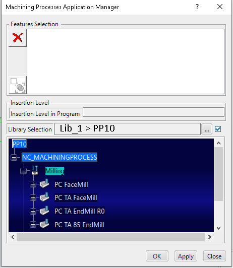
    The Machining Processes Application Manager opens.

  2. Click the ... command next to Library Selection and search a library using the Search in the Top Bar.
  3. Select a library class in the search results.
  4. In the Activities Process Tree, select the required manufacturing program.

    This is inserted into the Insertion level in Program in the Machining process Application Manager.

  5. Select UserFeature in the Manufacturing View, Sort by features.
    This applies the selection in the Feature Selection in the Machining process Application Manager.

    Optional: Using the Group option.

    By default, the selection of several features applied to one Machining Process results in the application of this Machining Process (all the included MO) for each selected feature.

    With the Group option, the group of Machining features is the single input for all Machining Operations defined in Machining Process.

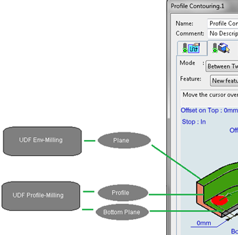
    For example, if you defined a Profile Contouring Operation, with three geometric expressions:

    • One for the definition of Top from a User Feature of type (UDF1 Env-Milling).
    • One for the definition of Bottom from a User Feature of type (UDF2 Profile-Milling).
    • One for the definition of Guide from the same User Feature of type (UDF2 Profile-Milling).

    For the application of the Machining Process containing the Profile Contouring Operation, select two User Features created previously in your Product, of type UDF1 Env-Milling and UDF2 Profile-Milling. Select the Group option , and then the Machining Process and Apply. The operation Profile Contouring is created and references the two User Features UDF1Env-Milling.1 and UDF2Profile-Milling.1.

    Note: With the Group option, when a geometric expression is solved by one UDF of the Feature Selection list, the other UDFs are ignored. This replacement occurs one at a time, except in the case of position definition for Axial Operation. For example, you can define a Geometric Expression on Position during the Apply. In this case, if the Feature Selection contains several UDFs of the same type that resolve the Geometric Expression, then the number of positions equal the number of valid UDF.
  6. Click OK.

    The Activities Process Tree.


    Note: Tool Queries that are attached to instantiated objects are performed either in the current Machining Operations Manufacturing Cell.

  7. Optional: Click Drilling and then Compute Tool Path .
    Where applicable, the tool is also associated automatically if it is assigned from the Formula in Tool Query Machining Operation.