Selecting Edges to Define Geometry | |||||
|
| ||||
-
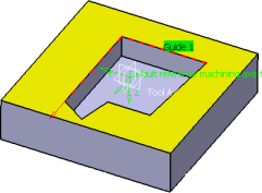
Click the icon representing the geometry to define.
The Edge Wizard appears like this

in all Machining Operations with the exception of the Multi-Axis Flank Contouring operation: the context menu item Use curves as part starts the following Edge Wizard: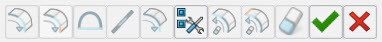
Note: Any hidden geometry selected using these commands is not taken into account in subsequent tool path computations. For more information, refer to the rules described in Influence of the Hide/Show Status of Selected Elements.See Selecting Faces to Define Geometry for
 icon
icon -
To select a belt of edges:
- Select an edge.
-
Click Navigate on Belt of Edges
 .
.
All the edges that are tangent to the one you have selected are selected. -
To select edges up to a given edge:
- Select two edges that are tangent (to give the direction of selection) .
-
Click Navigate on Edges Until an
Edge
 .
.
- Select a third edge.
All the edges between the start and a stop edges that are tangent are selected. -
To close a contour with a line:
Note: Not available with Multi-Axis Flank ContouringA straight line is inserted from the beginning of the contour to the end of it.
-
To insert a line on gaps:
-
Click
Insert Lines on Gaps

- Select one point as the beginning of the line and a second point as the end of the line.
Note: Not available with Multi-Axis Flank ContouringA line is created between those two points. -
Click
Insert Lines on Gaps
-
Click
Extend Last Selected Edge

An extension line is added to the last selected element of the current contour, in the same direction as this element. The length of the extension line is defined either by an Extension Value or by a Limiting Element. You can repeat Extend Last Selected Edge according to your need: each time you click Extend Last Selected Edge, an extension line is added after the previous one. Added extension lines is analyzed in the Geometry Analyser.
-
Click Reset Selection to Step Back
 The last selection reverts to a previous status given by a number of steps back defined in the Option dialog box.
 -
Click
Reset Selection to Stop Edge
 The last edge selections is reset up to the last stop edge.
 -
Click
Reset All Selections
 All the selections you have done are reset.
 -
To define selection options, click
Options
 The Options dialog box appears and contains the following options:
- In Multi-Axis Flank Contouring operations you have the Reverse Propagation bar with the Max Steps Forward 10, Steps back 1.
- In Turning Machining operations you have the Link types: Automatic, Line insert, Linear extrapolation, Axial radial, Radial axial
- In all other Machining Operations, Automatic, No link, Line insert, Linear extrapolation
The options available are:
- Link Types
- Applies a global link type for managing gaps during contour selection:
- Reverse Propagation
- During the edge selection, reverses the direction in which the following edges are to be selected.
- Propagation Domains
-
By default, only the edges included in the current Body (or OpenBody) is selected.
- Add
- Lets you select new bodies in the work area.
- Maximum Gap and Maximum Angle
- During automatic propagation, if there is more
that one possible edge for selection, the best candidate is selected according to
the following criteria:
- The gap between the last selected edge and the candidate edge must be less than the Maximum Gap.
- The angle between the tangent of the candidate edge and the tangent to the
last selected edges must be less than the Maximum
Angle. If there is still more than one candidate, the one that
makes the smallest angle is preferred. Note: The maximum value of angle supported is 180 degree.
- Max Steps Forward
- When navigating on a belt of edges, propagation stops when the number of steps (or edges) forward is reached. In this case the label Next? appears at the end of the last selected edge to prompt a user action.
- Steps Back
- When resetting previous edge selections, specifies the number of edges (or steps) that is reset.
- Limiting Element
- For Extend last Selected
Edge, defines the length of the extension line added to the current contour.
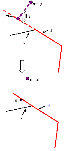
- If you select a point as the Limiting Element, the
length of the extension is defined by the projection of the point onto the
extension, as described below: 1 - Extended Last Selected Edge, 2 - Limiting
Element "Point", 3 - 90 deg, 4 - Last selected edge, 5 - Other connected edge
in part, 6 - Extended Length Element.
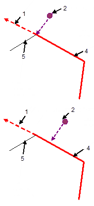
A message is displayed when an extension cannot be added because the projection of the selected point coincides with the last point of the last selected element, or lies in the opposite direction. 1 - Direction of Extension, 2 - Limiting Element "Point", 4 - Last selected edge, 5 - Other connected edge in part.
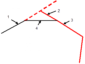
- If you select an edge as the Limiting Element, the
length of the extension is defined by the intersection of the edge and the
last selected element. 1 - Limiting Element "Edge" selected by the user, 2 -
Extended Length Element, 3 - Last selected edge, 4 - Other connected edge in
part.
A message is displayed when an extension cannot be added, for example when the selected edge and the last selected element are parallel, or lie in different planes.
- If you select a point as the Limiting Element, the
length of the extension is defined by the projection of the point onto the
extension, as described below: 1 - Extended Last Selected Edge, 2 - Limiting
Element "Point", 3 - 90 deg, 4 - Last selected edge, 5 - Other connected edge
in part, 6 - Extended Length Element.
- Extension Value
- For Extend last Selected Edge, defines the length of the extension line.
- Deep Selection
- When selected, lets you select the edges hidden
by overlapping faces.
By default, Deep Selection is not selected.
- Search in Plane
-
- This check box applies to Navigate
on Belt of Edges
,
Navigate on Edges Until an Edge
,
and Automatic Link Types.
- Once you have selected the Search in Plane checkbox,
proceed as explained above for each command. The only difference is that the
first two non-colinear edges you select define a plane (shown in yellow),
example,
or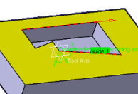 Notes:
- If you select only one edge, an error message is displayed.
- If you select more than two edges, only the last two ones are taken in account to define the plane.
- Once the plane has been defined, candidate edges are searched only in this
plane, making the definition of the required contour quicker and easier:
- Search in Plane is not selected:

- Search in Plane is selected:

- Search in Plane is not selected:
By default, Search in Plane is not selected.
- This check box applies to Navigate
on Belt of Edges
