Selecting Geometry | ||
| ||
-
Select some geometry.
Only the part to machine is mandatory but you can also select :
- The check element,
- The safety plane,
- A top plane,
- A bottom plane,
- A start plane,
- An end plane,
- Inner points,
- The limiting contour,
- The offset on the part (double-click Offset on part:0mm),
- The offset on the check element (double-click Offset on check:0mm).
Refer to each Machining Operation for more details.
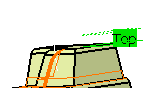
The corresponding portion of the icon turns from red to green.Note: The status color codes are as follows:- Green (or the current value of Valuated parameters): all the requested data are defined,
- Orange (or the current value of Optional parameters): data are defined, but modifications may be necessary,
- Red (or the current value of Required parameters): data definition is required.
- The colors of Valuated parameters, Optional
parameters, Required parameters are defined in
Me
 > Preferences > App Preferences > Simulation > Machining
.
> Preferences > App Preferences > Simulation > Machining
.
-
Select another geometry:
- Click a face definition area and use the Faces Selection tab,
- Click a contour definition area and use the Edges Selection tab,
- Right-click an element definition area: choose Body(ies) if you wish to machine a whole part and not just an area on it, or Select zones if you wish to select zones.
-
In the Feature pull-down window, choose a pre-defined area
like: Surface Feature.4.
Notes:
- Use Offset Groups and Features when defining geometry.
- The types of selection by default (reached by clicking a sensitive zone) are adapted to the types of the elements to select (bodies for a part to machine, but faces for check elements, for instance).
- The context menu 's vary also with the type of elements to select.
- Define planes by selecting a point or a plane in the work area.
-
Set an Offset on all of the planes using the context menu over each plane. The offset is either positive or negative and is previewed in the
work area
before it is validated.
In the case of imposed planes, the offset value applies to all of the planes you have imposed. The tool passes through all of the planes defined by the offset and not through the planes that are imposed. One advantage of this is that if the top surface of the part is flat and you have defined an Offset on part of, for example of 1mm, you can define the same offset on the imposed planes so as to ensure that there are no residual material remaining on the top surface.
-
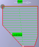
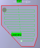
Use Part
Autolimit and the limiting contour individually or together to define the
area you want to machine.
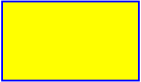
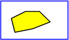
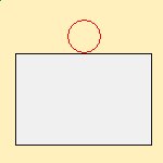
In the pictures:
- The blue outline is the part edge,
- The yellow part is the area that is to be machined,
- The black line is the limiting contour:
- If you activate Part Autolimit, the yellow area (shown
in the image) is machined and the tool contact point stops on the edge of the
part (the tool does not go beyond the edge of the part).
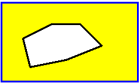
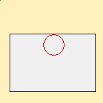
- If you use a limiting contour, only the area inside the limiting contour is
machined.
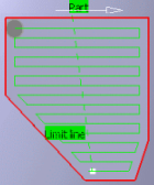
- If you wish to machine the area outside the limiting contour, choose
Outside as the Side to
machine.
- If you activate Part Autolimit, the yellow area (shown
in the image) is machined and the tool contact point stops on the edge of the
part (the tool does not go beyond the edge of the part).
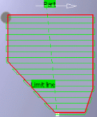
-
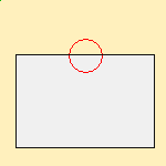
Once the limiting contour is defined, you can also define the following
parameters:
- Stop
position: Specifies where the tool stops:
- Outside stops the tool outside the limit line,
- Inside stops the tool inside the limit line,
- On stops the tool on the limit line.
- Outside stops the tool outside the limit line,
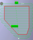
- Offset : Starting from the previous
position (Inside, Outside,
On) a positive value of the offset increases the area to
machine, a negative value reduce this area:
- Stop position=On, no Offset
- Stop position=On, Positive Offset

- Stop position=On, Negative Offset
- Stop position=Inside, no Offset
- Stop position=Inside, Positive Offset
- Stop position=Inside, Negative Offset

- Stop position=Outside, no Offset

- Stop position=Outside, Positive Offset
- Stop position=Outside, Negative Offset

- Stop position=On, no Offset
You can now either:- Run the operation on the part,
- Store the operation that you have just defined, or
- Define other parameters in the machining strategy, tool data, speeds and rates, or macro data tabs first.
- Stop
position: Specifies where the tool stops: