Creating Points and Lines with the Program Wizard | ||
| ||
 .
.
Create Limit Lines by Projecting a Sketch or a Polyline
You can create limit lines with Limit Lines Projection Wizard.

Create Limit Lines by Picking Points
You can create limit lines with Limit Lines Creation Wizard.
-
Click Limit Lines Creation Wizard
 .
The dialog box is displayed.
.
The dialog box is displayed. -
Select the Part body on which you are going to create the line.
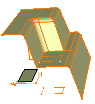
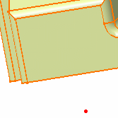
The lines are created from the projection of the picking positions onto the support body along the normal to the screen. If you pick a point outside the support body, the projected polyline starts at the intersection between the support and the line between the first and the second pick:

-
Click OK to validate the creation.
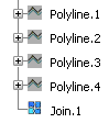
The polylines are created in the selected Geometrical set. If a join has been created, the polylines are sent to the NoShow while the Join only is visible.