Creating a Track Using Cumulative Snap | |||
| |||
-
From the
Simulation section of the action bar,
click
New Track
 .
The Track Authoring context toolbar appears.
 -
Select the product to move.
The Robot snaps on to the product you selected (if you selected several products, the Robot is attached to the first one you selected). The context toolbar proposes a set of commands for Track authoring and the Experience Player appears.
The Track Authoring dialog box can be accessed by clicking Track Authoring
 at the
right edge of the work area.
-
Select the
Track Properties
tab in the
Track Authoring dialog box.
The Number of Moving Objects area indicates the number of products you have selected.
-
Click
Cumulative Snap
 in the context toolbar.
The part to be snapped is selected and highlighted in the geometry area. The Track Authoring dialog box, Experience Player, and Track context toolbar disappear. The Cumulative Snap dialog box appears.
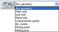
Note: The Cumulative Snap dialog box above shows the rotation options that become available when you select geometry on the parts.-
 inverts the snap direction by U-axis rotation
-
 inverts the snap direction by V-axis rotation
-
-
On the part for which you are creating the track (in this case,
the phone cover), select a geometric element. This element serves as that
part's first constraint (for example, the bottom line of the bottom of the
frame), and click.
Notes:
- You can enter more precise coordinates using the Parameters for Robot Manipulation dialog box. To access this dialog box, right-click the Robot and select Edit.
As you select geometry, an image beneath the pointer previews the type of geometry you select. See the line under the pointer in the image below.
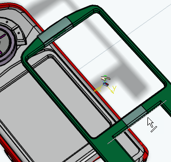
-
Select the first constraint on the stationary (receiving)
component (in this case, the phone front pocket).

The first coincidence constraint is created. The part being snapped is displaced in accordance with the first constraint.

-
Create the second coincidence.
-
Click a geometric element on the part to be snapped (for
example, the right bottom line of the phone cover).

-
Select a geometric element on the receiving component (for
example, the right bottom line of the phone cover pocket).

The second coincidence constraint is created. The cover is displaced in accordance with the second constraint.
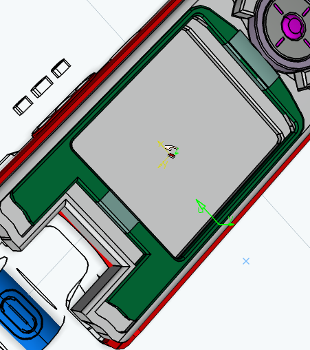
-
Click a geometric element on the part to be snapped (for
example, the right bottom line of the phone cover).
-
Create the third coincidence constraint.
-
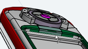
Select a line at the top of the cover frame that is
perpendicular to the line clicked in the first step, but in the same plane.
-
Select the corresponding constraining line on the phone cover
pocket.
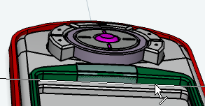
The third and final coincidence constraint is created. The phone cover is snapped into its pocket.

-
Select a line at the top of the cover frame that is
perpendicular to the line clicked in the first step, but in the same plane.
-
Close the
Cumulative Snap
dialog box.
The Track Authoring dialog box, Experience Player, and Track context toolbar reappear.
-
In the
Track Authoring dialog box, click
OK.