Collision Checking | ||
| ||
Collision Checking
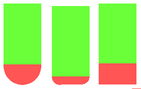
Collision checking can be performed on check and part elements, on the tool assembly (that is, the complete shape of the cutter plus its holder) or on the cutting part of tool (red part of following tools).
The cutting part of the tool is the lower component of the tool (see picture below) but not the part of the tool defined by the cutting length (Lc). For a ball nose tool, the cutting part is the lower half sphere; for a bull-nose tool, the lower half torus; for a cylindrical tool, the lower cylinder.

Check
- Offset on check
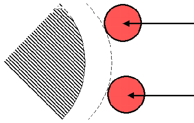
- Defines the minimum distance between the cutter and the fixture,
used to limit the tool path.
- The fixture is represented by diagonals.
- The tool paths are represented by the arrows.
- The offset on check is represented by the dotted line.

Note: You can apply a positive or negative offset on the check.