Creating a Multi-Axis Flank Contouring Operation in Combin Tanto Mode | ||||
|
| |||
- From the Surface Machining section of the action bar, click Multi-Axis Flank Contouring
 .
.
A Multi-Axis Flank Contouring entity is added to the manufacturing program.
The Multi-Axis Flank Contouring dialog box appears directly at the Geometry tab
 .
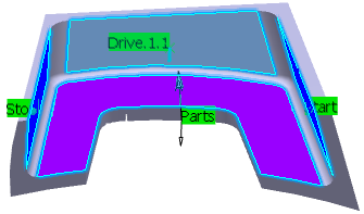
.The parts, drives and start/stop areas of the sensitive icon are colored red indicating that this geometry is required. All other geometry is optional.
-
Still in the Geometry tab:
- Click the red part surface in the icon then select the desired surface in the work area.
- Click the red drive surface in the icon then select the desired drive in the work area (Drive 1).
- Click the start and stop areas in the icon then select the desired limiting elements in the work area.
The surfaces of the icon are colored green indicating that this geometry is now defined. In the picture below,- The drive is shown in light blue.
- The Stop and Start are shown in dark blue.
- Go to the Strategy tab
 to specify the parameters of the machining operation:
- Guiding Strategy to Spine contour
- Machining
- Machining tolerance
- Max discretization step
- Max discretization angle
- Do not select Close tool path
- Max distance between steps
- Manual direction (for example Auto)
- Stepover
- Tool path style (for example One way)
- Sequencing to Radial first
- Radial Strategy
- Max distance between paths
- Number of paths
- Axial
- Mode to By offset
- Distance between steps
- Number of levels
- Tool Axis
- Guidance to Combin Tanto
- Contact height
- Tilt angle
- Lead angle
- Leave fanning distance
- Approach fanning distance
- Do not select Control fanning using tool parameter
- Position on guide curve to Auto
- Offset on guide curve
- Use of guide curve to If needed
In this example, Finishing Parameters, High Speed Milling (HSM) Parameters and Cutter Compensation Parameters are not required.
- Go to the Tools tab
 to select a tool.
 - Go to the Feeds and Speeds
tab
 to specify the feedrates and spindle speeds for the machining operation.
 - Go to the Macros tab
 to specify the transition paths (approach and retract motion,
for example).
to specify the transition paths (approach and retract motion,
for example). -
Click Display or
Simulate to check the validity of the machining operation.
