Applying Local Modifications to a Multi-Axis Flank Contouring Operation | ||||
|
| |||
- From the Surface Machining section of the action bar, click Multi-Axis Flank Contouring
 .
.
A Multi-Axis Flank Contouring entity is added to the manufacturing program.
The Multi-Axis Flank Contouring dialog box opens directly at the Geometry tab
 .
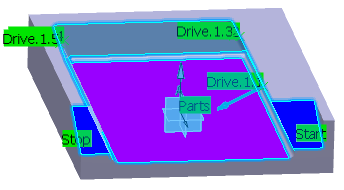
.The parts, drives and start/stop areas of the sensitive icon are colored red indicating that this geometry is required. All other geometry is optional.
- Still in the Geometry tab:
- Select the part surface.
- Select the drive surfaces (Drive 1 to Drive 5) either manually or using the Face Wizard.
- Select the start and stop limiting elements.
- Set a 1mm offset of the drive surfaces.
The selected geometry is indicated on the part. In the picture below:
- Drives are in light blue.
- Stop and Start are in dark blue.
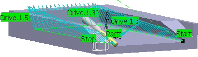
- Go to the Strategy tab
 to specify
the Tanto Fan tool axis guidance.
to specify
the Tanto Fan tool axis guidance.The other Strategy parameters can be left at the default values. The default Feeds and Speeds, and NC macros options can also be used.
-
Click Display or
Simulate to check the validity of the machining operation.
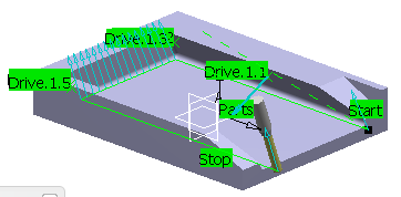
- Go to the Tools tab
 to select a tool.
 -
Click Display or
Simulate to check the validity of the modifications.
Tanto replaces Tanto Fan on first and last drives.
-
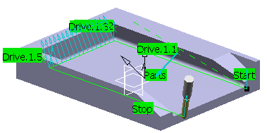
Click the 4-axis constraint symbol (Optional 4X plane) in the
Strategy tab
and select
an edge.Note: The 4-axis constraint can only be applied in Normal to part and Tanto tool axis guidance modes.
-
Click Display or
Simulate to check the validity of the machining operation.
The 4-axis constraint is applied on the first and last drives.
-
Click Display or
Simulate to check the validity of the modifications.
Note: The local reduction can be combined with the Feedrate reduction in corners options in the Feeds and Speeds tab
 .The feedrate reduction is applied on the third drive.