Creating a Multi-Axis Flank Contouring with Non-Adjacent Drives on Different Solids | ||||
|
| |||
- From the Surface Machining section of the action bar, click Multi-Axis Flank Contouring
 .
.
A Multi-Axis Flank Contouring entity is added to the manufacturing program.
The Multi-Axis Flank Contouring dialog box opens directly at the Geometry tab
 .
.The parts, drives and start/stop areas of the sensitive icon are colored red indicating that this geometry is required. All other geometry is optional.
-
Still in the Geometry tab:
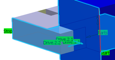
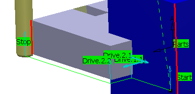
- Select the part surface (underside of gray solid, for example).
- Select the start and stop limiting elements.
- Select a first drive on the flank of the blue solid and the second on the flanks of the gray solid.
Those drives are not adjacent: They belong to different solids. Stopping and Restarting conditions must be defined on non-adjacent drives.
Arrows appear on the drives indicating the orientation for each adjacent section. - Make sure those arrows are oriented outward.Note: Arrows appear whenever necessary to indicate the orientation for the drive selection. Make sure that they are correctly oriented.

- Still in the Geometry tab, right-click the drive surfaces area
in the sensitive icon
and select
Local Modifications. The Local Drive Surfaces dialog box appears.
- Modify the first drive:
- Double-click line 1.The Local Drive Surface 1 dialog box appears.
- Set the Stopping condition to To.
- Click >> to access the Local Drive Surface 2 dialog box.
- Set Restarting direction to Left.
The Local Drive Surfaces dialog box is updated.
Note: Right-click in the Local Drive Surfaces dialog box to access a number of context commands:- Column Order and Column Filter for managing the columns of information that are shown.
- Properties for accessing the dialog box of the selected local drive.
- Reset to reset local drive selection in the list.
- Copy, Cut and Paste for managing the list of local drives.
- Double-click line 1.
- Go to the Tools tab
 to select a tool.
 -
Click Display or
Simulate to check the validity of the machining operation.

- Click OK to create the machining operation.