- From the Surface Machining section of the action bar, click Multi-Axis Contour-Driven
 . .
A Multi-Axis Contour-Driven entity is added to
the manufacturing program.
The dialog box opens at the Geometry tab
 .
-
Go to the Strategy tab
 to specify parameters for:
- Guiding Strategy to Spine contour
- Machining
- Tool path style (e.g. Zig zag)
- Machining tolerance
- Max discretization step
- Max discretization angle
- Radial
- Stepover (e.g. Scallop height)
- Scallop height
- Tool Axis
- Tool axis mode (e.g. Lead and tilt)
- Guidance (e.g. Fixed lead and tilt)
- Lead angle
- Tilt angle
-
Click the view direction arrow (V) and select the part
surface. The surface normal is used as the view direction.
-
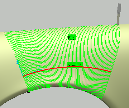
In the sensitive icon,
click the red Guide 1 curve and select the
guide curve in the model.
- Go to the Tools tab
 to select a tool. to select a tool. - Go to the Feeds and Speeds tab
 to specify the feedrates and spindle speeds for the machining operation. to specify the feedrates and spindle speeds for the machining operation.
- Go to the Macros tab
 to specify the machining operation transition paths (approach
and retract motion, for example). to specify the machining operation transition paths (approach
and retract motion, for example).
-
Click Display or
Simulate to check the validity of the machining operation.
- The tool path is computed.
- A progress indicator is displayed.
- You can cancel the tool path computation at any moment before 100% completion.
- Click OK in the Display or
Simulate dialog box, and again in the main dialog box to create the machining operation.
The tool path is created.
|