Creating an Multi-Axis Spiral Milling Operation | ||||
|
| |||
- From the Surface Machining section of the action bar, click Multi-Axis Spiral Milling
 .
A Multi-Axis Spiral Milling entity is added to the manufacturing program. The dialog box opens at the Geometry tab
.
A Multi-Axis Spiral Milling entity is added to the manufacturing program. The dialog box opens at the Geometry tab .
. -
Still in the Geometry tab:
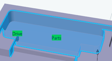
- Click the red area representing the part to machine.
The dialog box disappears.
Select the part.

Double-click anywhere in the work area to validate the selection and revert to the dialog box. - Click the area representing the guide faces.
The dialog box disappears to let you select the guide faces.
Double-click anywhere in the work area to validate the selection and revert to the dialog box.
- Click the red area representing the part to machine.
The dialog box disappears.
Select the part.
-
Go to the Strategy tab
 to select the High Speed Milling check box in the HSM tab.
- Go to the Tools tab
 to select a tool.
 - Go to the Feeds and Speeds tab
 to specify the feedrates and spindle speeds for the machining operation.
- Go to the Macros tab
 to specify the machining operation transition paths (approach
and retract motion, for example).
to specify the machining operation transition paths (approach
and retract motion, for example).
-
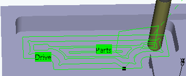
Click Display or
Simulate to check the validity of the machining operation.
- The tool path is computed.
- A progress indicator is displayed.
- You can cancel the tool path computation at any moment before 100% completion.