- From the Surface Machining section of the action bar, click Multi-Axis Sweeping
 . .
A Multi-Axis Sweeping entity is added to
the manufacturing program.
The dialog box opens at the Geometry tab
 .
-
Still in the Geometry tab,
choose Select faces in the context menu of
Part in the icon
then select the desired face in the work area.
The part surface of
the icon is now colored green indicating that this geometry is now
defined.
-
Go to the Strategy tab
 to specify parameters for:
- Machining
- Tool path style (e.g. Zig zag)
- Machining tolerance
- Max discretization step
- Max discretization angle
- Radial
- Stepover (e.g. Scallop height)
- Scallop height
- Stepover side
- Tool Axis
- Tool axis mode to 4-Axis lead/lag
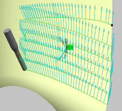
-
Define the guiding plane of the machining operation:
- Click the view direction arrow (V) and select the part surface.
The surface normal is used as the view direction. - Click the start direction arrow (S) and set the
direction.
- Click the 4-Axis Constraint arrow (N in the work area or
the arrow normal to the plane in the sensitive icon)
and set this direction in the dialog box that appears.
This is the
normal to the plane in which the tool axis is constrained. You can also click the overall machining direction arrow
(M in the work area) to reverse this direction.
- Click Preview in the dialog box to verify the parameters that you have specified.
A message box appears giving feedback about this verification. - Go to the Tools tab
 to select a tool. to select a tool. - Go to the Feeds and Speeds tab
 to specify the feedrates and spindle speeds for the machining operation. to specify the feedrates and spindle speeds for the machining operation.
- Go to the Macros tab
 to specify the machining operation transition paths (approach
and retract motion, for example). to specify the machining operation transition paths (approach
and retract motion, for example).
-
Click Display or
Simulate to check the validity of the machining operation.
- The tool path is computed.
- A progress indicator is displayed.
- You can cancel the tool path computation at any moment before 100% completion.
- Click OK in the Display or
Simulate dialog box, and again in the main dialog box to create the machining operation.
The tool path is created.
|