Creating a Multi-Axis Tube Machining Operation Around Guide | ||||
|
| |||
- From the Surface Machining section of the action bar, click Multi-Axis Tube Machining
 .
A Multi-Axis Tube Machining entity is added to the manufacturing program. The dialog box opens at the Geometry tab
.
A Multi-Axis Tube Machining entity is added to the manufacturing program. The dialog box opens at the Geometry tab .
.
- Still in the Geometry tab:
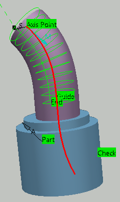
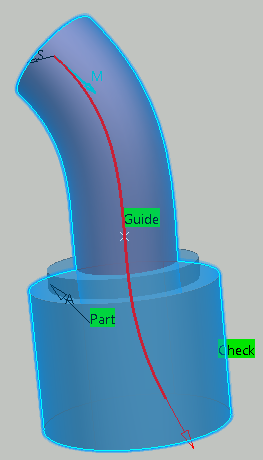
- Click the red area representing the part to machine.
The dialog box disappears.
- Select the part. Double-click anywhere in the work area to validate the selection
and revert to the dialog box.

The red area has turned green. - Right-click the area representing the check.
The dialog box disappears.
- Select the check.
Double-click anywhere in the work area to validate the selection
and revert to the dialog box.

The check area has turned green.
- Click the red area representing the part to machine.
- Go to the Machining Strategy
 tab.
tab.
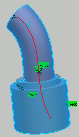
- Make sure the Guiding strategy is set to Around guide.
- Click the line in the sensitive icon and select the curve.
- Set the Side to machine to Inside.
- Click the end point in the sensitive icon and select an end point.
- Go to the Tool Axis tab.
- Set Tool axis mode to Thru a point.
- Click the To point that has appeared in the
sensitive icon and select the top end of the curve.

- Go to the Tools tab
 and select a T-Slotter tool.
 -
Click Display or
Simulate to check the validity of the machining operation.
- The tool path is computed.
- A progress indicator is displayed.
- You can cancel the tool path computation at any moment before 100% completion.