- From the Surface Machining section of the action bar, click Multi-Axis Tube Machining
 . .
A Multi-Axis Tube Machining entity is added to
the manufacturing program.
The dialog box opens at the Geometry tab
 . - Still in the Geometry tab:
- Click the red area representing the part to machine.
The dialog box disappears.
- Select the part.
Double-click anywhere in the work area to validate the selection
and revert to the dialog box.
The red area has turned green.
-
Go to the Machining Strategy tab
 . .
- Set the Guiding strategy to Helical.
- In the Machining tab,
set Driving tool points to Tool tip,
Side to machine to Inside and
Zone to Cavity.
-
Go to the Tool Axis tab:
- Set Tool axis mode to Thru a point.
- Change From to To.
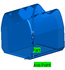
- Select a point as the Axis Point.
- The part is shown in blue.
- The axis point in shown as the red dot.
 -
In the sensitive icon:
-
Right-click the axis
and
select As guiding axis in the context menu.
The icon turns to. 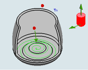
-
Click the red dot and select a point as the center of the cavity to machine.
- Click the arrow representing the tool axis and set the tool axis to (0,0,-1).
The tool axis A (black arrow) specifies where the cavity is located. The Machining direction M (orange arrow) specifies that the machining is performed from bottom to top. 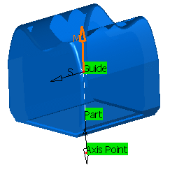
- Go to the Tools tab
 : :- Select a Lollipop tool.
- Define its diameter.
-
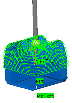
Click Display or
Simulate to check the validity of the machining operation.
- The tool path is computed.
- A progress indicator is displayed.
- You can cancel the tool path computation at any moment before 100% completion.

- Click OK in the Display or
Simulate dialog box, and again in the main dialog box to create the machining operation.
Multi-Axis Tube Machining.1 is created in the process
table.
-
Copy Multi-Axis Tube Machining.1 and edit it:
- Change its name to Multi-Axis Tube Machining.2.
- Set Side to machine to Outside.
- Change To to From.
- Select a line as the guiding curve and
reverse the tool axis.

Note:
The center of the cavity is one of the end points of the guiding
curve.
If you define a relimiting point, this point will become the center
of the cavity.
-
Click Display or
Simulate to check the validity of the machining operation.
- The tool path is computed.
- A progress indicator is displayed.
- You can cancel the tool path computation at any moment before 100% completion.
- Click OK in the Display or
Simulate dialog box, and again in the main dialog box to create the machining operation.
Multi-Axis Tube Machining.2 is created in the process
table.
|