- From the Surface Machining section of the action bar, click Multi-Axis Tube Machining
 . .
A Multi-Axis Tube Machining entity is added to
the manufacturing program.
The dialog box opens at the Geometry tab
 . -
Go to the Machining Strategy tab and select a Guiding strategy mode:
- Around guide,
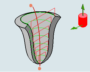
that lets you choose between two tool path styles: Zig zag or One way. - Along guide,
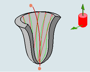
that lets you choose between three tool path styles: Zig zag, One way or Back and forth. - Helical.
-
Select a guide:
- Click the curve in the sensitive icon and
select one in the work area, or right-click the curve in the sensitive icon and
select As guiding axis,
Another sensitive icon is displayed. 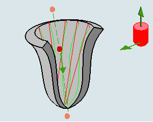 - Click the red point and the arrow to select one point and an axis
direction.
When this icon is displayed: - The context menu changes to bring
you back to the other selection mode.
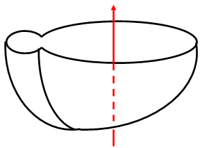
- The machining direction (M arrow) is displayed at one end of the
guide.
- Click this arrow to invert the machining direction if necessary.
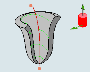
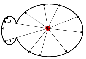
- Areas that cannot be reached by the beams issued from the guide
are not machined.
In the pictures below,
- The guide is represented in red.
 represents areas that are not
machined. represents areas that are not
machined.
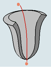
View normal to the guide
-
Select the limiting points (represented by the dots below).
- Click the limiting point in the sensitive icon and select a
point in the work area or right-click the limiting point in the sensitive icon and
select On guide in the context menu.
A red dot appears on the guide. - Drag the red dot to the
required position.
-
Define the tool axis:
-
Click the vertical arrow to define the tool axis.
-
Click the horizontal arrow to define the start direction.
The start direction can be:
- The beginning of each pass if the Guiding strategy
is set to Around guide.
- The location of the first pass if the Guiding
strategy is set to Along guide.
- or the beginning of the helix if the Guiding
strategy is set to Helical.
- Set the other parameters of the machining operation as required.
|