Creating a Multi-Pockets Flank Contouring Operation | ||||
|
| |||
- From the Surface Machining section of the action bar, click Multi-Pockets Flank Contouring
 .
Note: This machining operation is dedicated to the machining of part showing multiple pockets with an obvious view direction as shown in the scenario below. Multi-Pockets Flank Contouring is not suitable for this part as it has no obvious view direction.
A Multi-Pockets Flank Contouring entity is added to the manufacturing program. The Multi-Pockets Flank Contouring dialog box opens at the Geometry tab. - Still in the Geometry tab:
- Click Part in the sensitive icon and select the part to machine.
- Double-click anywhere in the work area to validate your selection and revert to the main dialog box.
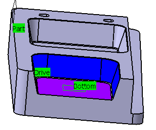
- Click Drive and select faces as shown below in dark blue.
- Click Bottom and select the bottom of the part as shown below in purple.

- Click OK in the Face Selection toolbar to validate the selection and revert to the main dialog box.
- Go to the Stepover tab.
- Set the Distance Between Paths.
- Set the Number of paths.
- Go to the Tools tab
 to select a tool.
 - Click Display or Simulate to check the validity of the machining operation.
- Add the faces shown in dark blue to the drive.

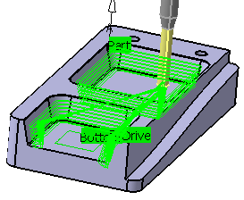
Click Display or Simulate to check the validity of the machining operation.The tool path is computed and displayed:
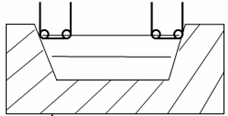
The ZLevel-like path is compputed as follows:- In this first step, the passes are computed following a ZLevel-like strategy
with a tool axis along the view direction, taking into account the part,
the check and limit lines. The part and check are represented by the diagonals.

-
The tool rolls along the drives represented in blue:

Starting from the previous position, the tool rotates around the contact point so that it becomes tangent to the drives. -
The tools comes in contact with the bottom represented in blue:

If bottom finish is required, in the last path the tool comes into contact with the bottom. -
Last step: multi-path and chaining management:

- In this first step, the passes are computed following a ZLevel-like strategy
with a tool axis along the view direction, taking into account the part,
the check and limit lines. The part and check are represented by the diagonals.
- Click OK to validate and exit the dialog box.
