Supporting NC Machines with Multiple Tool Chains | ||
| ||
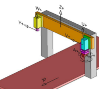
The Inverse Kinematics (IK) supports machines with multiple tool chains, allowing these machines to be used for tool path simulation and checking reachability.
| Examples of Machines | |
|---|---|
 |  |
Refer to the existing User Interface in the Device Building Application to create and assign Numeric Kinematics. Details of assigning IK parameters are available at Content and Simulation > Industrial Engineering > Production Equipment Definition > Advanced Tasks, Assigning Inverse Kinematics.
Using this command, Create New IK Chain, you can create multiple IK chains. Each IK chain is assigned a separate IK Solver Type, Numeric Inverse.
In the TCP Convergence parameters, select the drop-down corresponding to Roll and set it to No. Once the IK kinematics is defined with multiple chains, you create tool mount points for each chain. This is using the existing User Interface in MTB, for creating tool-mount points.
Then define the Tool Profile's corresponding to each of the tool-mount points and assign the appropriate IK chain to each of the tool profiles. Use the Tool Profile![]() command available in Device Building.
command available in Device Building.