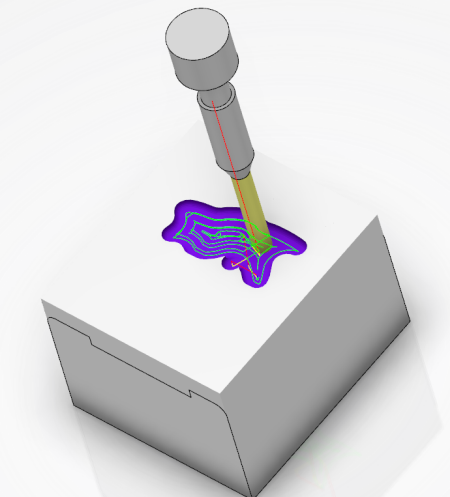
Simulate a Complete Tool Path
You can simulate a complete tool path and use options to customize the tool path.
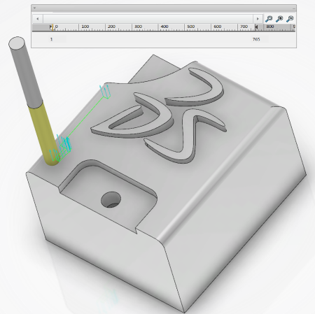
- From the experience player, click Play Forward
 .The tool path is simulated.
- To customize the tool path:
- Next to the tool path line, select a simulation option such as Each Position of Tool
 .
. - Double-click Play in the Compass to simulate the tool path.
The tool path appears with the simulation option taken into account.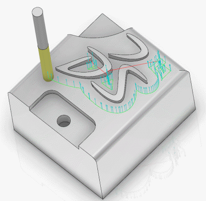
- Next to the tool path line, select a simulation option such as Each Position of Tool
- Optional: To display information on the tool path:
- Next to the tool path line, click Machine Information
 .
. - In the Controller State Display During Simulation panel, select the Tool Path Information check box.
The Tool Path Information panel appears with information on the tool path. The panel includes the following: Time, Feedrate, Spindle, X, Y, Z, I, J, and K.Note: X, Y, Z, and I, J, K coordinate values appear in two separate lines and every expander in the panel is collapsed to reduce the size of the panel. If there is only one expander in the panel, then it is in the expanded state. The expand/collapse states of the expanders within this panel are remembered across multiple simulations and the previous state is restored when you start a new simulation. - Next to the tool path line, click Machine Information
| Tip:
To simulate the tool path of another machining operation or manufacturing program, click the operation or program in the Activities Process Tree and click Play Forward
. |
 arrow to the
required point.
arrow to the
required point.
 arrow to the
required point.
arrow to the
required point.
 . Alternatively, select the
  .
.