|
Instruction Support
FANUC Instruction Support The following table summarizes the level of support for each FANUC file by the DELMIA FANUC translator and DELMIA simulation. | Fanuc File | Level of Support | DELMIA Equivalent | Comment | | LS-file | Supported | Task | | | PE-file | Supported | Task | | | sysframe.va, sysvars.va, payload.dat (PAYLOAD only), or utool.dat (UTOOL only) | Supported | Tool Profile | PAYLOAD also supported. | | sysframe.va, sysvars.va or uframe.dat (UFRAME only) | Supported | Object Frame Profile | | | syspress.va or sgparam.dat | Supported | Applicative Profile | Spot servo pressure and backup schedules | | WDELAY.SCD | Supported | Applicative Profile | Weld time schedules. This is NOT a Fanuc controller file, but user created. | | sysspot.va | Supported | Applicative profile | R30 Spot servo pressure and backup schedules | | sysdist.va | Supported | Applicative profile | R30 Spot servo pressure and backup schedules | | sysstrok.va | Supported | Applicative profile | R30 Spot servo pressure and backup schedules | | posreg.va or posreg.dat | Supported | Tag or jointtarget | Position registers PR[<index>] with Cartesian (tag) or Joint target values. | | numreg.va | Supported | Wait instruction timeout value. | Integer Registers for WAIT R[<index>] Fanuc instruction and for register speed (i.e. R[<index>]mm/sec) | | sysmacro.va | Supported | Task name | Maps a macro call in Fanuc to a task call in V6. | | dcspos.va | Supported | Safety zones | Tool safety zones and tool volumes |
Using RRS Virtual Robot Files In the table above, when RRS is connected, the files with a .dat extension are read from the RRS virtual robot directory, if found. The RRS virtual robot folder is created from a FANUC controller backup using the FANUC virtual robot utility. This utility also generates the DAT-files and stores them in a sub folder of the virtual robot named *_rrs. For RRS, this virtual robot folder is then placed in the Virtual Robots folder and, when connecting with RRS, you specify the relative path to this virtual robot. On the RCS server, create a windows file share called Virtual Robots to share the directory that contains all of the virtual robots. If you cannot share that directory, you must copy the virtual robots folder onto your computer into C:\ProgramData\FANUC\Shared\Off Line\Virtual Robots. In the example below, the virtual robot folder is HMA2_SPO2_R22B. The
virtual robot has a sub folder HMA2_SPO2_R22B_rrs that contains the
DAT-files. The RCS server v0003deu generally has a directory
C:\ProgramData\FANUC\Shared\Off Line\Virtual Robots. Share this folder on
the RRS server. The FANUC translator will then look in \\v000deu\Virtual
Robots\HMA2_SPO2_R22B\HMA2_SPO2_R22B_rrs for the DAT-files.

Table 1. RRS .dat file read from virtual robot directory| 1 |  | File \\v0003deu\Virtual Robots\HMA2_SPO2_R22B\HMA2_SPO2_R22B_rrs\posreg.dat used for position register data. | | 2 | | File \\v0003deu\Virtual Robots\HMA2_SPO2_R22B\HMA2_SPO2_R22B_rrs\uframe.dat used for uframe data. | | 3 | | File \\v0003deu\Virtual Robots\HMA2_SPO2_R22B\HMA2_SPO2_R22B_rrs\utool.dat used for utool data. | | 40 |  | POSREG.DAT found in RRS server files and posreg.va found in upload directory. RRS server data will be used. | If one of the files is found in both the RRS
directory and in the current upload directory a warning
will be displayed and the RRS data will be
used.
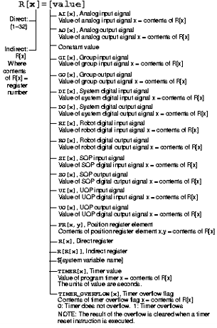
The following table summarizes the level of support for each FANUC instruction by the DELMIA FANUC translator and DELMIA simulation. Any instruction which does not appear in this table is uploaded as a comment instruction and is not used in simulation. | FANUC TP Instruction | Level of Support | DELMIA Instruction | Comments | | Motion Instructions | | J | Partial Support | Robot Motion | Some motion options are not supported for simulation. Indirect addressing of positions is not supported. | | L | Partial Support | Robot Motion | | C | Partial Support | Robot Motion | | UTOOL_NUM | Partial Support | Robot Motion or V6 Comment | A custom instruction is created only if needed to preserve the file format. Setting the value for individual groups is not supported for simulation. | | UFRAME_NUM | Partial Support | | PAYLOAD | Partial Support | V6 Comment | Not simulated. Tool profile not updated on upload. | | Spot Instructions | | SPOT | Supported | Spot Operation | | | BACKUP | Partial Support | V6 Comment | Not simulated | | ISO CONTACTOR | Partial Support | V6 Comment | Not simulated | | GUN CONTACTOR | Partial Support | V6 Comment | Not simulated | | RESET STEPPER | Partial Support | V6 Comment | Not simulated | | RESET WELDER | Partial Support | V6 Comment | Not simulated | | RESET WATER SAVER | Partial Support | V6 Comment | Not simulated | | Arc Instructions | | Arc Start | Supported | Arc Operation | | | Arc End | Supported | Arc Operation | | | Search and Shift Instructions | | SEARCH | Partial Support | V6 Comment | Not simulated | | TOUCHOFFSET | Partial Support | V6 Comment | Not simulated | | Logic Instructions | | JMP LBL | Partial Support | Goto | Indirect addressing or labels is not supported. | | LBL | Supported | Label on another instruction | | | IF | Partial Support | Condition | Indirect addressing of variables is not supported. | | END | Supported | Return | | | CALL | Partial Support | Run (procedure) | Indirect addressing is not supported. | | Macro | Partial Support | V6 Comment, Grab, Release | Not simulated unless it is identified as a grab or release instruction. | | SELECT | Supported | Test/Case | | | ELSE | Partial Support | V6 Comment | Not simulated. | | IO and Arithmetic | | R[…]= | Partial Support | Assign | On upload (with very few exceptions) the FANUC TP expression is converted into a DELMIA expression. However, converting the DELMIA expression to a FANUC expression is not always possible on download. Indirect addressing is not supported. System variables are not supported. Multi-dimensional arrays are not supported. | | DO[…]= | Partial Support | Assign | | RO[…]= | Partial Support | Assign | | AO[…]= | Partial Support | Assign | | GO[…]= | Partial Support | Assign | | WO[…]= | Partial Support | Assign | | PR[…]= | Partial Support | V6 Comment | Not simulated. | | UTOOL[…]= | Partial Support | V6 Comment | Not simulated. | | UFRAME[…]= | Partial Support | V6 Comment | Not simulated. | | WAIT | Partial Support | Wait | The On+ (leading edge) and Off- (trailing edge) FANUC TP wait options are not supported. The TIMEOUT option is not supported. Indirect addressing is not supported. Using a variable to specify the time for a pure delay (WAIT R[1]sec) is not supported. | | PULSE | Partial Support | Pulse | For both upload/download the pulse duration must be set to a constant value. For download the target data type must be Boolean and the Pulse duration must be between .1 and 25.5 seconds. | | LPOS | Partial Support | V6 Comment | Not simulated. | | JPOS | Partial Support | V6 Comment | Not simulated. | | Other | | ! (Comment) | Supported | V6 Comment | |
Converting Files to FANUC Binary Format
Preparing for Upload A standard FANUC robot backup contains only
the binary files. To upload files into DELMIA, you must convert
the TP-files (binary) to LS-files (text). This can be done on the
robot controller, or using FANUC's OlpcPRO software. On the robot
controller, LS files can be listed using the file menu and copied
to an external device (drive). With the OlpcPRO software, you can load a
controller backup and then save as LS-files.
DELMIA also makes use of system
variable files, if available, during upload to create the tool and
object frame profiles along with some other data. The binary
system variable (SV) files must be converted to text files
(VA-files). This can be done either on the robot controller by
copying all VA-files, or by using OlpcPRO.
Loading Files on Controller after Download DELMIA generates LS-files (text) during the
download for each task. To load these files on a FANUC robot
controller, you must have the FANUC "Ascii Upload" option
installed on the controller, or you must convert to TP-files
(binary) before loading them. LS to TP conversion can be done using
FANUC's OlpcPRO software.
It is not possible to load system variables
on a FANUC controller. Any system variable information (such as
UTOOLs, UFRAMEs and position registers) must be entered manually at
the controller. The sysvars.ls file generated during download
contains much of the information required to manually
enter at the robot controller.
Instruction Details
Unsupported Instructions To ensure that the file generated on download is a valid FANUC task, any instruction that is not supported is skipped. A message is displayed indicating that the DELMIA instruction is not supported by the FANUC TP language. If an unsupported logic instruction contains other instructions (such as the instructions inside a DO WHILE loop), they are also skipped. Such instructions must be removed from the DO WHILE loop to be downloaded. Goto A DELMIA Goto instruction is translated
into a JMP LBL. In DELMIA, the label is defined on a specific
instruction.
On upload the label is set on the
first instruction after the LBL. The label is named
"x : comment". If there are no more instructions, a custom activity
is created with the name "LBL[x : comment]". If the LBL
referenced by a GOTO does not exist in the program, a warning is displayed and the Goto instruction does not point to any
label.
On download, the LBL instruction is output
just before the instruction that has the DELMIA label defined on
it. If the label name is in the format "x : comment", where x is a
number, then the comment is used in the LBL instruction and x
is used for the label number. If the label name is not in that
format and the DELMIA label name contains a number, that number
is used for the label, unless the number is not unique.
Otherwise, the label number is automatically generated.
Indirect label addressing is not supported.
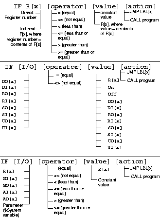
ConditionA DELMIA Condition instruction is translated into an IF. The expression for the IF must conform to the FANUC IF rules. Additionally, multiple expressions can be joined with AND and OR expressions, however AND and OR cannot be mixed. On download, any instructions in the DELMIA ELSE clause are ignored. If it is not empty, a warning is displayed. The DELMIA THEN clause must contain only one instruction and that instruction must be a run for a procedure or a Goto. If the first instruction is not a Goto or run, the Condition instruction is skipped and a warning is displayed. If any other instruction exists in the sequence, it is ignored and a warning is displayed. On upload, a condition instruction with one instruction in the THEN sequence is created. The expression is an exact translation of the FANUC expression. FANUC supported IF expressions (from FANUC Robotics SYSTEM R-J3iB HandlingTool Setup and
Operations Manual):
Custom
A custom instruction text is downloaded into
the task exactly as is. On upload, any unsupported instruction is
created as a custom instruction with the name of the custom
instruction being the TP instruction's text. The TP line number and
ending semicolon are removed from the instruction on upload, and added back on download.
Grab/ReleaseOn download, the instruction name is downloaded exactly as is. This is generally the macro name used to grab the product. On upload, if the name of a macro instruction contains the phrase “grab” or “pick”, a grab activity is created. If it contains “release” or “drop”, a release activity is created. The part to grab or release is specified in the PartGrabbed parameter of the Fanuc Controller Profile. AssignA DELMIA assign instruction is translated into a Fanuc TP assignment. The expressions for the assignment must conform to the Fanuc TP assignment restrictions on
download. A Fanuc register is a local variable in DELMIA. For register assignments, simple
expressions are allowed.
Output IOs are also assigned with this
statement. This includes DO, RO, AO, GO, UO, SO. The Fanuc PULSE
syntax of output assignment is not supported. If encountered, the
instruction is uploaded as a custom activity. Output IOs can
either be assigned a constant value or the value of a
register.
On upload, TIMER and TIMER_OVERFLOW are not
supported. A warning is displayed and a custom instruction is created from the assignment.
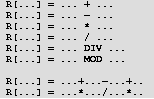
WaitA DELMIA Wait instruction is translated as a Fanuc TP WAIT instruction. On download, the expression for the wait must conform to the Fanuc wait expression syntax. The Fanuc “WAIT time” expression format corresponds to a DELMIA Wait instruction with the
expression set to the constant “false.” The DELMIA timeout value is the time. This is a pure
delay. If a register is used for the Fanuc wait time and the corresponding register is found in
a numreg.va file, the register value will be used: [*NUMREG*]$NUMREG Storage: CMOS Access: RW :
ARRAY[500] OF Numeric Reg [34] = 4.296000
For download the syntax WAIT R[34] must be used in the display name because a variable in the
DELMIA TimeOut value is not supported.
If the WAIT instruction has a TIMEOUT with label it will be uploaded using the
WaitGotoOnTimeout template.

The WaitGotoOnTimeout is uploaded only if the robot simulation templates have been imported. The
Timeout value is defaulted to 30 sec but is read from the system.va file: [*SYSTEM*]$WAITTMOUT
Storage: CMOS Access: RW : INTEGER = 3000.

On upload, WAIT instructions are uploaded as custom activities if the parameter “CommentWaitSignal” of the profile “Fanuc Controller Profile” is set to true. This is the default value. The robot program will pause during simulation at the WAIT instruction unless all of the robot’s IO have been set up and the full station behavior is being simulated. The On+ (leading edge) and Off- (trailing edge) Fanuc TP wait options are not supported. If
encountered, the WAIT instruction is uploaded as a custom instruction.

Run (procedure) A DELMIA run instruction that is
calling a procedure is translated into a Fanuc CALL
instruction.
Run instructions can have arguments. The
argument expression in the run instruction must conform to the
FANUC TP argument requirements. An argument can be
a constant, string, local variable (R[x]) or procedure input
variable (AR[x]). TP allows for a maximum of ten arguments. A warning is displayed if more than
ten are used, however the arguments are included. The run instruction arguments have a direction.
Only input arguments are supported by FANUC TP.
| DELMIA argument direction | FANUC | Download Result | | In | Supported | Argument Registers (AR) Used | | Out | Not Supported | The output variable will be substituted with a Register (R) | | InOut | Not Supported | The input variable will be substituted with a Register (R) |
Robot Motion The following table indicates the level of support for different motion options. Any unsupported options are stored in an applicative profile attached to the motion instruction so they can be downloaded again. | Fanuc Motion Option | Support Level | DELMIA Equivalent | Description | Translation Notes | | J, L, C | Supported | Joint, Linear, Circular | motion type | Fanuc circular moves have two positions, one via, and one target | | <speed>%, <speed>sec, <speed>mm/sec, <speed>deg/sec | Supported | Motion Profile | Speed | Time, % or absolute motion basis. Speeds specified as a R[<index>] are supported. A numreg.va file in the same directory as the uploaded file(s) will be searched for the appropriate R[<index>] to set the speed. A warning is displayed if the register is not found. | | CNT<0-100>, CD<distance>, FINE | Supported | Accuracy Profile | Accuracy | If CNT is used then accuracy type speed is used and the % speed set to the CNT value. If CD is specified accuracy type distance is used and the distance is set to the CD value. Flyby is On for both CNT and CD types. If FINE is used Flyby is Off, accuracy type is speed with % set to 0. | | ACC<accel> | Supported | | Acceleration | Accel value % used to set the motion profile acceleration. | | RTCP | Supported | | Fixed tool center point motion planning. | Fixed TCP move. | | WJNT | Supported | | Wrist joint orient mode | Sets the target orientation mode to wrist joint. | | P[<index>:<comment>] PR[<index>:<comment>] | Supported | Position with Comment | Position or position register | For P[] the target is in the POS section of the program uploaded. For PR[] a posreg.va in the same directory as the uploaded file(s) is searched to find the position register. A warning is displayed if the position register is not found. The comment will set the V6 motion Position Comment. | | sysframe.va | Supported | Tool and Object Profiles | System variable file with UTOOL/UFRAME definitions. | Tool and object profiles are created or updated from this file if it exists. |
Applicative Profile Motion Options The Fanuc Controller allows options to be used for each robot motion command. The following motion options are upload/downloaded to applicative profiles that are linked as described for each option. Any motion options not included here or in the table above will be stored in a "Fanuc Motion Profile" applicative profile which is linked to the robot motion. - Corner Speed (CS=*)
The Fanuc corner speed specifies the speed to be used along the robots trajectory in a flyby move. The syntax is P[1] 100mm/sec CNT100 CS=50mm/sec. The applicative profile "Fanuc Corner Speed Parameters" is used to store this value and is linked to the motion instruction's accuracy profile. | Parameter | Measure | Default | Uploaded Value | | CornerSpeed | Velocity | -1 | Set based on CS=<speed> motion option. |
The corner speed parameters are displayed in a dialog accessed from the accuracy profile.

- Path Option (PTH)
The Fanuc path option allows a move to be treated as a path rather than treating each move independently. The syntax is P[1] 100mm/sec CNT100 PTH. The applicative profile "FanucPath" is used to store this value and is linked to the motion instruction using the same interface that is used for other motion instruction profile types such as motion or accuracy profiles. | Parameter | Measure | Default | Uploaded Value | | PthOption | Boolean | False | Set based on PTH motion option. |
- Extended Velocity (EV)
The Fanuc extended velocity option allows extended axes velocities to be set. The syntax is P[1] 100mm/sec CNT100 EV100% or P[1] 100mm/sec CNT100 Ind.EV100%. The applicative profile "Fanuc Extended Velocity Parameters" is used to store this value and is linked to the motion instruction's motion profile. | Parameter | Measure | Default | Uploaded Value | | EVMode | Integer | 1 | Set based on EV option used. 0 - NoEV, 1 - Simultaneous, 2 - independent | | EVSpeed | Ratio | 100 | Percentage of maximum speed |
The extended velocity parameters are displayed in a dialog accessed from the motion profile.
Payload The Fanuc payload instruction allows an index to be specified for a move or series of moves. The syntax is PAYLOAD[1] where the index 1 points to a group of Fanuc system variables that give the mass, cog, and inertia for the current tool. The applicative profile "Fanuc Payload Parameters" is used to store this value and is linked to the motion instructions tool profile. Below is the parameter and default value. | Parameter | Measure | Default | Uploaded Value | | Index | Integer | 1 | Set based on PAYLOAD[index] instruction |
In addition to setting this index and linking the PAYLOAD to the tool profile, the uploader will also read the system variables for mass, cog and inertia using these to set the corresponding values of the tool profile. Override Speed The Fanuc override instruction allows a percent speed to be specified for a move or series of moves. The syntax is OVERRIDE = 100%, meaning that the motions are run a certain percentage of programmed speed. The applicative profile "Fanuc Override Speed" is used to store this value and is linked to the motion instruction using the same interface that is used for other motion instruction profile types, such as motion or accuracy profiles. | Parameter | Measure | Default | Uploaded Value | | _override_spd | Ratio | 100 | Set based on OVERRIDE 100% |
Spot Welding Only servo guns are
supported for spot welding. Gun changes are not supported. Spot instructions are
output as a move with a SPOT option.
J P[10] 100% CNT100 SPOT[P=16,S=66,BU=2]
The upload and download behavior of SPOT
links the applicative profiles created from uploading the SGPARAM.DAT
and WDELAY.SCD files with the spot profile so that the uploaded
values are used in simulation. Other spot profile parameters are also configured with the appropriate values.
If any of the SGPARAM.DAT, WDELAY.SCD, or
SPRESS.VA files are not present during upload, the spot profile is created with default values for these profiles.
In the most common cases, the SPOT
instruction will be automatically generated on download based on
the parameters in the spot profile. In these cases, the spot
profile will also be configured during upload so that simulation
with and without RRS will be as accurate as possible. When necessary, you can override the auto generation feature
and specify the exact SPOT syntax in the spot profile
name.
The parameters used in simulation are EQ, P, S, BU, SD and
ED. The following table lists all of the known
arguments to the SPOT instruction used in RJ3 and R30 controllers, and describes any limitations with regard to auto
generation of the instruction during download and simulation
support.
| Measure | Specify for each gun? | Optional? | Can be set to Variable? | Meaning | Supported for Auto Generation / Simulation | | P | Integer | Yes | Yes | Yes | Pressure schedule | Only as Integer | | S | Integer | Yes | No | Yes | Weld schedule | Only as Integer and cannot be omitted. | | BU | Integer | Yes | Yes | Yes | Backup schedule | Only as Integer. | | EQ | Integer | Yes | Yes | Yes | Equalization (RJ3 only) | Only as Integer | | SD | Integer | Yes | Yes | Yes | Start distance (R30 only) | Only as Integer | | ED | Integer | Yes | Yes | Yes | End distance (R30 only) | Only as Integer | | t | Double | Yes | Yes | Yes | Thickness (R30 only) | Only as Integer/Double | | WID | String | No | Yes | No | Weld ID (R30 only) | OLPdata Position Comment |
- Pressure Schedule
-
On upload the spot servo pressure schedules will be uploaded into an applicative profile named "Fanuc Spot Pressure Schedule". Values will be uploaded from a SGPARAM.DAT file. | Parameter | Default Value | Measure | | Index | 1 | Integer | | GunNumber | 1 | Integer | | COMMENT | | String | | WELD_PRESS | 0.0kgf | Force | | THICKNESS | 0.0m | Length | | PUSH_DEPTH | 0.001m | Length | | GUNSAGVAL | 0.0m | Length | | SOFT_TOUCH | True | Boolean | | SFTCH_TA | .005m | Length | | SFTCH_TB | 0.0m | Length | | SYNC_TA | 0.0 | Length | | SYNC_TB | 0.0 | Length | | SYNC_TERM | -1 | Ratio | | SYNC_ACC | 100 | Ratio | | DECEL_RATE | 100 | Ratio | | PRSCLS_TERM | -1 | Ratio | | PRSCLS_ACC | 100 | Ratio | | SFTOPN_TA | 0.0m | Length | | SFTOPN_TB | 0.0m | Length | | SFTOPN_TERM | 0 | Ratio | | GUN_OPEN | False | Boolean | | AWAY_TERM | 0 | Ratio | | AWAY_ACC | 100 | Ratio | | PRESS_TIME | 0s | Time | | TIME_OUT | 5s | Time | | STOKE_LEN | 0.0m | Length | | MOTION_TYPE | 0 | Integer | | SPEED | 100 | Ratio | | TERM_TYPE | 1 | Integer | | TERM_VAL | 100 | Ratio | | PS_ACC_USE | 0 | Integer | | ACC_USE | True | Boolean | | ACC_VALUE | 100 | Ratio | | PS_PATH_USE | 0 | Integer | | PATH_USE | False | Boolean | | USE_MANUAL | False | Boolean |
These values come directly from the SGPARAM.DAT or the SYSPRESS.VA file if it exists in the same folder as the LS-files being uploaded. SGPARAM.DAT is a file generated by FANUC's "Virtual Robot Converter" software. SYSPRESS.VA can be exported from Fanuc RJ3 and R30 controllers. It has the same format for all controllers. The file format for the SGPARAM.DAT file is as follows. $SGSCH1[1].$COMMENT = 'Weld1'
$SGSCH1[1].$WELD_PRESS = 1.000000e+02
$SGSCH1[1].$THICKNESS = 2.500000e+00
$SGSCH1[1].$PUSH_DEPTH = 2.000000e+01
$SGSCH1[1].$GUNSAGVAL = 0.000000e+00
$SGSCH1[1].$SOFT_TOUCH = TRUE
$SGSCH1[1].$SFTCH_TA = 3.000000e+01
$SGSCH1[1].$SFTCH_TB = 1.000000e+01
$SGSCH1[1].$SYNC_TA = 1.000000e+01
$SGSCH1[1].$SYNC_TB = 0.000000e+00
$SGSCH1[1].$SYNC_TERM = 100
$SGSCH1[1].$SYNC_ACC = 150
$SGSCH1[1].$DECEL_RATE = 4.800000e+01
$SGSCH1[1].$PRSCLS_TERM = 0
$SGSCH1[1].$PRSCLS_ACC = 150
$SGSCH1[1].$SFTOPN_TA = 1.000000e+01
$SGSCH1[1].$SFTOPN_TB = 0.000000e+00
$SGSCH1[1].$SFTOPN_TERM = 100
$SGSCH1[1].$SFTOPN_ACC = 150
$SGSCH1[1].$GUN_OPEN = TRUE
$SGSCH1[1].$AWAY_TERM = 0
$SGSCH1[1].$AWAY_ACC = 150
$SGSCH1[1].$PRESS_TIME = 0.000000e+00
$SGSCH1[1].$TIME_OUT = 5.000000e+00
$SGSCH1[1].$STROKE_LEN = 0.000000e+00
$SGSCH1[1].$MOTION_TYPE = 0
$SGSCH1[1].$SPEED = 100
$SGSCH1[1].$TERM_TYPE = 1
$SGSCH1[1].$TERM_VAL = 100
$SGSCH1[1].$PS_ACC_USE = 0
$SGSCH1[1].$ACC_USE = TRUE
$SGSCH1[1].$ACC_VALUE = 150
$SGSCH1[1].$PS_PATH_USE = 0
$SGSCH1[1].$PATH_USE = FALSE
$SGSCH1[1].$USE_MANUAL = TRUE
The Index is used for download of the pressure schedule. The other values are used to set applicative profile and/or spot profile values. These values are used by RRS for servo weld gun simulation. The pressure schedule for Fanuc is an index into the $SGSCH1 (gun1) and $SGSCH2 (gun2) array. A P=1 indicates that for that spot weld the $SGSCH1[1] system parameters are used. The index is stored in the "Fanuc Spot Pressure Schedule" applicative profile. Several of the $SGSCH1 values are used to set spot profile values, shown in the following tables. Table 2. Spot Profile Model Parameter values | Parameter | Measure | Specify for each gun? | Uploaded Value | | Profile Name | String | No | SPOT[P=1,S=1,BU=1] | | Gun Enabled | Boolean | Yes | True if Gun present i.e. P=(1,1) for both gun 1 and gun 2 pressure schedules | | Part Thickness | Double | Yes | Set based on $SGSCH1[1].$THICKNESS | | Approach Enabled | Boolean | No | Set based on $SGSCH1[1].$SOFT_TOUCH. For R30 controller always FALSE. R30 no longer uses approach/depart moves and SD/ED correspond to pressure start/end. | | Pressure Start Enabled | Boolean | No | True | | Pressure End Enabled | Boolean | No | True | | Backup Enabled | Boolean | No | Set based on $SGSCH1[1].$GUN_OPEN. For R30 controller always FALSE. R30 no longer uses approach/depart moves and SD/ED correspond to pressure start/end. | Table 3. Spot Profile Approach Move Parameter values | Parameter | Measure | Specify for each gun? | Uploaded Value | | Approach Moving Tip Clearance | Length | Yes | Set based on $SGSCH1[1].$SFTTCH_TA | | Approach Stationary Tip Clearance | Length | Yes | Set based on $SGSCH1[1].$SFTTCH_TB | Table 4. Spot Profile Pressure Start Move Parameter values | Parameter | Measure | Specify for each gun? | Uploaded Value | | Pressure Start Moving Tip Clearance | Length | Yes | Set based on $SGSCH1[1].$SYNC_TA | | Pressure Start Stationary Tip Clearance | Length | Yes | Set based on $SGSCJ1[1].$SYNC_TB | | Pressure Start Accuracy Profile | Accuracy Profile | No | Set based on $SGSCH1[1].$SYNC_TERM (i.e. 100 sets to "100%") | | Pressure Start Acceleration | Percent | No | Set based on $SGSCH1[1].$SYNC_ACC | Table 5. Spot profile Pressure move and weld values | Parameter | Measure | Specify for each gun? | Uploaded Value | | Pressure Move Accuracy Profile | Accuracy Profile | No | Set based on $SGSCH1[1].$PRSCLS_TERM (i.e. 100 sets to "100%") | | Pressure Move Acceleration | Percent | No | Set based on $SGSCH1[1].$SPRSCLS_ACC | | Pressure Move Push Depth | Length | Yes | Set based on $SGSCH1[1].$PUSH_DEPTH | | Speed Factor | Percent | Yes | Set based on $SGSCH1[1].$DECEL_RATE. | Table 6. Spot profile Pressure end move values | Parameter | Measure | Specify for each gun? | Uploaded Value | | Pressure End Moving Tip Clearance | Length | Yes | Set based on $SGSCH1[1].$SFTOPN_TA | | Pressure End Stationary Tip Clearance | Length | Yes | Set based on $SGSCH1[1].$SFTOPN_TB | | Pressure End Accuracy Profile | Accuracy Profile | No | Set based on $SGSCH1[1].$SFTOPN_TERM (i.e. 100 sets to "100%") | | Pressure End Acceleration | Percent | No | Set based on $SGSCH1[1].$SFTOPN_ACC | Table 7. Spot profile Backup move values | Parameter | Measure | Specify for each gun? | Uploaded Value | | Backup Stationary Tip Clearance | Length | Yes | Set based on $SGSCH1[1].$SFTTCH_TB. Never used for R30 controller. | | Backup Accuracy Profile | Accuracy Profile | No | Set based on $SGSCH1[1].$AWAY_TERM (i.e. 100 sets to "100%"). Never used for R30 controller. | | Backup Acceleration | Percent | No | Set based on $SGSCH1[1].$AWAY_ACC. Never used for R30 controller. | The Fanuc Pressure Schedule applicative profile is linked to the Spot Profile. - Weld Schedule
-
On upload, the spot servo pressure schedules are uploaded into an applicative profile named "Fanuc Weld Schedule". The values are uploaded from a WDELAY.SCD file. | Parameter | Default Value | Measure | | Index | 1 | Integer | | WeldDelay | 0.25s | Time |
These values come directly from the WDELAY.SCD file if exists in the same folder as the LS-files being uploaded. WDELAY.SCD does not come from the FANUC controller and must be created by you. If this file does not exist, Fanuc weld schedules are created with a default weld delay of 0s. After upload, you can modify the weld delay values to match their pressure schedules. WDELAY.SCD uses the following format: 1,0.3
2,0.3
3,0.3
4,0.3
5,0.3
6,0.3
7,0.3
8,0.3
9,0.3
10,0.3
11,0.35
12,0.35
13,0.35
14,0.35
15,0.35
16,0.35
17,0.35
18,0.35
19,0.35
20,0.35
Index is used for download of the weld schedule. WeldDelay sets the weld delay in the spot profile. The weld schedule is used to indicate which weld delay value from the WDELAY.SCD file is used. The index is stored in the "Fanuc Weld Schedule" applicative profile. Table 8. Spot Profile Pressure Move and Weld Parameter values | Parameter | Measure | Specify for each gun? | Uploaded Value | | Weld Delay | Seconds | Yes | Set based on WDELAY.SCD indexed value (i.e. 1, 440 for index 1 and .440 seconds) | - Distance Schedule (R30 controller only)
- On upload, the spot servo distance schedules are uploaded into applicative profiles named "Fanuc Start Distance Schedule" and "Fanuc End Distance Schedule". Values are uploaded from a SYSDIST.VA file.
Table 9. Fanuc Distance Schedule default values (R30 controller only) | Parameter | Default Value | Measure | | Index | 1 | Integer | | GunNumber | 1 | Integer | | COMMENT | | String | | DIST_GUN | 0.0m | Length | | DIST_RBT | 0.0m | Length | | AP_TERMTYP | 0 | Integer | | AP_ACC | 100 | Ratio | | RT_TERMTYP | 0 | Integer | | RT_ACC | 100 | Ratio | These values will come directly from the SYSDIST.VA file if it exists in the same folder as the LS-files being uploaded. SYSDIST.VA can be exported from the R30 controller. The file format is as follows. $SGDST1[1].$COMMENT = 'Gun-5 RB-1'
$SGDST1[1].$DST_GUN = 5.000000e+00
$SGDST1[1].$DST_RBT = 1.000000e+00
$SGDST1[1].$RT_TERMTYP = 100
$SGDST1[1].$RT_ACC = 100
$SGDST1[1].$AP_TERMTYP = 100
$SGDST1[1].$AP_MOTYP = 0
$SGDST1[1].$AP_SPEED = 100
$SGDST1[1].$AP_ACC = 100
The Index is used for download of the SD/ED schedule. The other values are used to set applicative profile and/or spot profile values. These values will be used by RRS for servo weld gun simulation. The SD/ED distance schedules for Fanuc are indexes into the $SGDST1 (gun1) and $SGDST2 (gun2) array. A SD=1 indicates that for that spot weld the $SGDST1[1] system parameters will be used. The index is stored in the "Fanuc Start Distance Schedule" or "Fanuc End Distance Schedule" (for ED) applicative profile. Several of the $SGDST1 values are used to set spot profile values. Table 10. Fanuc Spot Profile Start Pressure Move Parameter values (R30 controller only) | Parameter | Measure | Specify for each gun? | Uploaded Value | | Pressure Start Moving Tip Clearance | Length | Yes | Set based on $SGDST1[1].$DST_GUN. | | Pressure Start Stationary Tip Clearance | Length | Yes | Set based on $SGDST1[1].$DST_RBT. | | Pressure Start Accuracy Profile | Accuracy Profile | No | Set based on $SGDST1[1].$AP_TERMTYP (i.e. 100 sets to "100%"). | | Pressure Start Acceleration | Percent | No | Set based on $SGDST1[1].$AP_ACC. | Table 11. Fanuc Spot Profile End Pressure Move Parameter values (R30 controller only) | Parameter | Measure | Specify for each gun? | Uploaded Value | | Pressure End Moving Tip Clearance | Length | Yes | Set based on $SGDST1[1].$DST_GUN. | | Pressure End Stationary Tip Clearance | Length | Yes | Set based on $SGDST1[1].$DST_RBT. | | Pressure End Accuracy Profile | Accuracy Profile | No | Set based on $SGDST1[1].$RT_TERMTYP (i.e. 100 sets to "100%"). | | Pressure End Acceleration | Percent | No | Set based on $SGDST1[1].$RT_ACC. | - Thickness Schedule (R30 controller only)
- On upload, the spot servo thickness value is uploaded into an applicative profile named "Fanuc Thickness Schedule". Values are uploaded from the t=<thickness> option in the Fanuc SPOT command.
Table 12. Fanuc Thickness Schedule default values (R30 controller only) | Parameter | Default Value | Measure | | Index | 1 | Integer | | GunNumber | 1 | Integer | | Thickness | 0.0m | Double | The Thickness is used for download of the t=<thickness> value. The Thickness value is used to set applicative profile and/or spot profile values. These values are used by RRS for servo weld gun simulation. Table 13. Fanuc Spot Profile Model Parameter values | Parameter | Measure | Specify for each gun? | Uploaded Value | | Part Thickness | Length | Yes | Set based on SPOT t=<thickness> value. | - Backup Schedule
On upload, the spot servo backup schedules are uploaded into an applicative profile named "Fanuc Backup Schedule". Values are uploaded from a SGPARAM.DAT file or a sysstrok.va file. Table 14. Backup Schedule default values | Parameter | Default Value | Measure | | Index | 1 | Integer | | GunNumber | 1 | Integer | | COMMENT | | String | | STROKE | 0.0m | Length | | USE_MANUAL | False | Boolean | These values come directly from the sparam.dat file or the sysstrok.va file if it exists in the same folder as the LS-files being uploaded. SGPARAM.DAT is a file generated by FANUC's "Virtual Robot Converter" software. SYSSTROK.VA can be exported from the RJ3 controller. The R30 controller has no backup move so these parameters are not used for that controller. Below is the file format. $SGBACK1[1].$COMMENT = 'BU1'
$SGBACK1[1].$STROKE = 2.000000e+01
$SGBACK1[1].$USE_MANUAL = FALSE
Index is used for download of the backup schedule. The other values are used to set applicative profile and/or spot profile values. These values is used by RRS for servo weld gun simulation. The backup schedule for Fanuc is an index into the $SGBACK1 (gun1) and $SGBACK2 (gun2) array. A B=1 indicates that the $SGBACK1[1] system parameters are used for that spot weld. The index is stored in the "Fanuc Backup Schedule" applicative profile. One of the $SGBACK1 values is used to set a spot profile value. Table 15. Spot Profile Backup Move Parameter values | Parameter | Measure | Specify for each gun? | Uploaded Value | | Backup Move Stroke | Length | Yes | Set based on $SGBACK1[1].$STROKE. Never used for R30 controller. | - Gun Parameters
Two of the $SGGUN1 values are used to set spot profile values. Table 16. Spot Profile Model Parameter values | Parameter | Measure | Specify for each gun? | Uploaded Value | | Close direction | Minus/plus | Yes | Set based on $SGGUN1.$SETUP.$TIPSLCOSDIR TRUE is plus | | Approach Direction | X, Y, Z | Yes | Set based on $SGGUN1.$SETUP.$RBTCLOSDIR 1,2 - X 3,4 - Y 5,6 - Z. Never used for R30 Controller. | - Additional Parameters
The Fanuc SPOT command has options for EQ in the RJ3 controllers: SPOT[EQ=1,P=1,S=1,EQ=1,BU=1] or SPOT[EQ=(1,1),P=(1,1),S=(1,1),EQ=(1,1),BU=(1,1)] (2 guns) These are uploaded/downloaded from SpotProfile scoped applicative profiles named "Fanuc Gun 1 EQ Parameters" and "Fanuc Gun 2 EQ Parameters".
In cases where the exact text of
the SPOT command is needed and individual attribute values must be ignored, the "Fanuc Controller Parameters" NameOverride can be
set to False. By default the attributes will be used.
Arc Welding Arc instructions are output as a move with an
Arc option.
L P[3] 800mm/sec FINE Arc Start[1]
L P[3] 800mm/sec FINE Arc End[1]
The translation of Arc welding instructions relies
on the Arc profile and also the Fanuc specific TPEARCStart and
TPEARCEnd profiles. Generally one arc profile is associated with
all arc operations for a single weld. A TPEARCStart profile is
associated with the arc profile start section and a TPEARCEnd
profile with the end section.
The speed parameter for the TPEArcStart and
TPEArcEnd is handled as follows: If the WeldSpeed parameter is linked
to the arc profile the speed for the move will be
WELD_SPEED.
L P[4] WELD_SPEED FINE Arc End[1] On upload, the TPEArcStart and TPEArcEnd applicative profiles are created and linked to an arc profile. The arc profile is named "Arc Start[1], End[1]" by default. If WELD_SPEED is used, the arc profile is named "Arc Start[1], End[1] WELD_SPEED".
Sealant Sealant instructions are output as a move with a SS/SE option. L P[3] 300mm/sec FINE SS[1]
L P[4] 300mm/sec FINE SE
Translation of sealant instructions relies on
the Fanuc-specific "Fanuc Seal Profile" applicative profiles. A
"Fanuc Seal Profile" is linked to a StartProcess or MidProcess
motion instruction. The "Fanuc Seal Profile" index parameter is
used to store the SS index. The SE is a sealant end and is handled
using an EndProcess motion instruction.
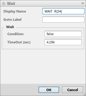
Paint
The following are Fanuc TPE paint commands and their corresponding DELMIA instructions.
| DELMIA Instruction |
Level of Support |
TPE Instructions |
Comments |
| Trigger Instruction of type change parameter immediate (no trigger plane) with paint
profile named PRESET[<index>]. |
Supported |
PRESET[<index>] |
The DELMIA paint profile will have values read from Fanuc system variable files. The
values set include Disk Rotation Speed, Flow Rate, Air Volume Regulation, and
Voltage. |
| Trigger Instruction of type ON/OFF immediate with paint profile named
PRESET[<index>] (based on last PRESET command seen, PRESET[1] by default). |
Supported |
GUN=ON/OFF |
|
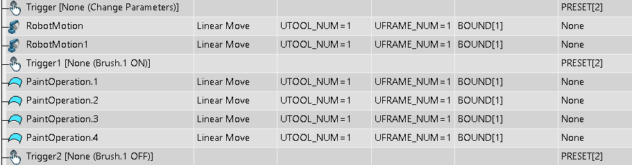
The FANUC PRESET value is uploaded into and downloaded from a DELMIA paint profile.
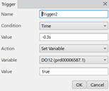
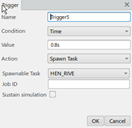
The PRESET and GUN commands are uploaded into and downloaded from DELMIA trigger
instructions.

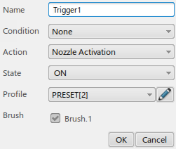
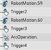
The paint sequence of setting the PRESET parameters and turning the gun ON/Off is shown
below:
Locked Position Registers A Position Register is a position that can be used across multiple programs. A position register is declared in a POSREG.va file as shown here. [*POSREG*]$POSREG Storage: CMOS Access: RW : ARRAY[2,100] OF Position Reg
[1,1] = 'HOME POSITION'
Group: 1 Config: N R U T, 0, 0, 0
X: 768.527 Y: 30.400 Z: -306.003
W: 90.000 P: 90.000 R: 0.000
In the Fanuc program the position register is used as follows: 7: !HOME POSITION ;
8:J PR[1] 30% CNT100 ;
Position register lock allows these registers to be uploaded/downloaded but limits modification. For cartesian targets it creates a locked tag that prevents modification unless the tag is unlocked. For Joint targets, a home position is created that can only be changed from the home positions command. - PR with joint values
Uploaded as a home position named
PR<index>. For example, PR[1] will
create a home position named PR1. The OLP data Position Type and
Position number attributes are not set.
Home positions are output as PR based on
the home name. If an uploaded home position is modified in the home
positions command, the move will still be downloaded as the same PR
with no warning. If the home position name is not in the format PR#
and the Position Number attribute is not set, then an unused
position register number will be used for the position and a
warning is displayed.
- PR with cartesian values
- Upload creates a locked tag named PR<index>. For example, PR[1] will create locked tag PR1.
Device TasksYou can upload and download device tasks for Fanuc robots with multiple motion groups. A task created for any type of device can be uploaded and downloaded. Any instruction already supported by the FANUC translator that can be created in a device task can be uploaded or downloaded. - Tool/objectframe
- DELMIA does not use tool or object frame profiles for device moves. However, FANUC programs still specify them. The UTOOL/UFRAME number is stored in a user profile called "Device Tool Profile" or "Device Object Frame Profile" that is automatically created on upload. During download, UTOOL 1/UFRAME 1 is used if no device tool or object frame profiles have been created. All other parameters such as the TCP and mass will be fixed at 0 and cannot be changed. These profiles do not impact simulation.
- Gear ratio
- Some FANUC programs for devices have joint values specified in degrees, but the simulation devices have linear joints. You can set the gear ratio and zero offset for each axis by creating a user profile and an attribute for each joint.
- Multiple Groups Device Mapping
- Device tasks that control multiple motion groups are supported for upload and download. The DELMIA motion group configuration should match the real controller. The FANUC translator is not fully aware of the motion group setup in DELMIA, so you must configure the ToolGroup OLP controller parameter to map the joints to the motion. This parameter determines which auxiliary axes values in the downloaded/uploaded program will map to EndOfArmTooling. Either of two formats can be used. The first is to set the Group number for all EndOfArmTooling axes. So ToolGroup=2 means all tool axes are in group 2. The second is to use a comma delimited value with the first axes number for each group. For example, if the task controls 14 joints, 7 joints in group 1 and 7 in group 2, specify the parameter as "1,8,*,*,*". This puts joints 1-7 in group 1 and joints 8 to the 14 in group 2.
- Called tasks for different motion groups
- If a device task calls another task that controls a different motion group or groups, you must upload the called tasks first. Copy the called tasks which control a different group into a separate directory, and upload those tasks. Then, copy the main tasks into a separate directory and upload them. The calls in the main task will be created to call the tasks which were already uploaded for the called task motion group.
Line/Rail Tracking
The following are Fanuc TPE track commands and their corresponding DELMIA Instructions.
| Delmia Instruction |
Level of Support |
TPE Instruction |
Comments |
| Wait conveyor referential instruction. |
Supported |
SELBOUND LNSCH[<index>] BOUND[<boundindex>] |
LNSCH index and BOUND boundindex are used to read system variable files to determine
the BOUND[<boundindex> track profile inbound and outbound values. The inbound value is
used in the Wait conveyor instruction. Track profile is used on all motion instructions in
that use the tracking UFRAME number. |
The SELBOUND command is uploaded into and downloaded from a wait conveyor instruction and
corresponding track profile. The track profile is automatically uploaded for line or rail
tracking, depending on the robot configuration.
The paint sequence of setting the PRESET parameters, moving to tracked targets and turning
the gun ON/Off is shown below.
Expressions
FANUC expressions used in IF, WAIT, Assignment,
and Argument passing are more restrictive than the DELMIA
expressions. On upload, with very few exceptions, the FANUC TP expression can be converted into a DELMIA expression. However,
converting the DELMIA expression to a FANUC expression is not
always possible on download.
If an error occurs converting an expression on
upload, the instruction containing the expression will be uploaded
as a custom instruction. If an error occurs converting an
expression on download, the instruction containing the expression
will be skipped. This prevents compile errors in the generated
program. In both cases, a warning is displayed.
Variable Conversion FANUC TP has a limited number of
variables. Each variable is an array, and all variables except
procedure arguments are global. DELMIA external IO, IO defined on
the robot, is mapped to one of the FANUC IO variables. DELMIA
local variables are mapped to registers (R[x]), and procedure IO
are mapped to arguments (AR[x]). On upload, the IO and variables
are automatically created.
On download, the corresponding FANUC IO or
variable is determined from the IO address. The IO address
also is used to determine the IO index, and should be in the
format VAR[x], where VAR is the FANUC variable name and x is the
index. For some variables, the port number can be used by itself. If
the IO address is not specified, an IO address is automatically
assigned to an unused value and a warning is displayed.
External IO must be declared of the appropriate
type in DELMIA. Group IO must be of type integer, analog IO must be
of type double, and all other IO must be of type Boolean. Variables
that can be Any Type are uploaded as variant, but can be of any
type during download. If the IO address in DELMIA specifies a type
that does not match, a warning is displayed and the type is ignored. For example, if a Boolean input has its address
specified as GI[1], then it will be downloaded as GI[1]. This may
result in an LS-file that cannot be converted into a
TP-file. Timer variables are supported with START, STOP, and RESET options. A register (R[x]) variable can also be assigned a Timer value.
|
FANUC Variable/IO
|
Variable Type
|
Direction
|
Location
|
Address
|
|
R[x]
|
Any Type
|
Local Variable
|
Robot or Procedure
[1]
|
R[x] or x
|
|
DI[x]
|
Boolean
|
Input
|
Robot
|
DI[x] or x
|
|
DO[x]
|
Boolean
|
Output
|
Robot
|
DO[x] or x
|
|
RI[x]
|
Boolean
|
Input
|
Robot
|
RI[x]
|
|
RO[x]
|
Boolean
|
Output
|
Robot
|
RO[x]
|
|
GI[x]
|
Integer
|
Input
|
Robot
|
GI[x] or x
|
|
GO[x]
|
Integer
|
Output
|
Robot
|
GO[x] or x
|
|
AI[x]
|
Double
|
Input
|
Robot
|
AI[x] or x
|
|
AO[x]
|
Double
|
Output
|
Robot
|
AO[x] or x
|
|
SI[x]
|
Boolean
|
Input
|
Robot
|
SI[x]
|
|
SO[x]
|
Boolean
|
Output
|
Robot
|
SO[x]
|
|
UI[x]
|
Boolean
|
Input
|
Robot
|
UI[x]
|
|
UO[x]
|
Boolean
|
Output
|
Robot
|
UO[x]
|
|
WI[x]
|
Boolean
|
Input
|
Robot
|
WI[x]
|
|
WO[x]
|
Boolean
|
Output
|
Robot
|
WO[x]
|
|
PR[x]
|
Not supported
|
|
|
|
|
$SystemVariable
|
Not supported
|
|
|
|
|
TIMER
|
Not supported
|
|
|
|
|
TIMER_OVERFLOW
|
Not supported
|
|
|
|
|
AR[x]
|
Any Type
|
Input,
|
Procedure
|
AR[x] or x
|
|
R[x]
|
Any Type
|
inout, output
[2]
|
Procedure
|
R[x] or x
|
|
Not supported
[3]
|
Any Type
|
Constant
|
Robot or Procedure
|
|
[1] Registers are always uploaded as global robot
IO.
[2] See the Run (procedure) section for details on how a procedure's IO are converted.
[3] Contestants are replaced by their literal value on
download.
The main limitation on upload is that FANUC indirect addressing is not supported. This is where the index of the variable or IO is specified as a register: "DI[R[1]]". Expression Conversion FANUC expressions are limited to a simple set of operations. | Category | Description | FANUC Operator | DELMIA Operator | | Binary Integer/Double | Plus | + | + | | Minus | - | - | | Multiply | * | * | | Division | / | / | | Integer Division | x DIV y | NA | | Modulus | x MOD y | mod(x,y) | | Power | NA | ** | | Unary | Negative | NA | - | | Not | NA | not | | Bitwise Not | NA | ~ | | Binary Comparison | Equals | = | = | | Not Equals | <> | <> | | Less Than | < | < | | Less Than or Equal | <= | <= | | Greater Than | > | > | | Greater Than or Equal | >= | >= | | Binary Boolean | And | AND | and | | Or | OR | or | | XOR | NA | xor | | Bitwise And | NA | & | | Bitwise Or | NA | | | | Left Shift | NA | << | | Right Shift | NA | >> | | Bitwise XOR | NA | ^^ | | Other | Grouping | NA | ( ... ) | | conditional (if) | NA | If ... then ... else ... |
The DIV operator does not have a
DELMIA equivalent. Any instruction which uses a DIV operator will
be uploaded as a custom instruction.
FANUC expressions do not support
functions. If any functions are encountered in the program, the
expression will be in error.
There are limits regarding how operations can be combined. Due to these limitations, operator
precedence and parentheses are not relevant in a valid FANUC
expression. If parentheses are encountered in an otherwise valid
expression, they will be removed on download and a message is displayed. | Description | FANUC Pattern | Limitation | | Addition, subtraction | ...+...-... | Maximum of 4 operators, can only contain + or - | | Multiplication, Division | ...*.../... | Maximum of 4 operators, can only contain * or / | | AND | ...AND...AND... | Maximum of 4 AND operators. AND and OR cannot be mixed. Value between the ANDs must be a comparison of 2 values using a binary comparison operator. DI[1]=On AND R[2]<5 | | OR | ...OR...OR... | AND and OR cannot be mixed. Maximum of 4 OR operators. Value between the ORs must be a comparison of 2 values using a binary comparison operator. DI[1]=On OR R[2]<5 | | All other operators | | Expression can only contain that single operator. |
Controller Parameters
The Fanuc Controller Parameters that were formerly created as a standalone applicative profile are now created as a scoped profile under the robot motion controller. The user interface for this can be found below. Below are the parameters for the current release.
Table 17. Fanuc Controller Parameters | Parameter | Measure | Purpose | Default Value | | ProgramFileEncoding | String | This parameter is used to set the encoding used in the robot program. (i.e. Shift-JIS) | | | CommentWaitSignal | Boolean | Used to treat all Wait signal instructions during upload as custom instructions. | False | | UseHexForUtool | Boolean | Used to determine if hexadecimal values can be used for utool numbers. Set to TRUE for R30 controller | False | | Digital_IO | Integer | This parameter determines the range of port numbers to use for DO/DI signals (by default 0-100). | 100 | | OrientMode | String | This parameter controls the orient mode that is uploaded to cartesian/tag targets. It can be changed to "1_axis", "3_axis", or "wrist". | 2_axis | | PartGrabbed | String | This parameter is used to set the grabbed part in an uploaded grab instruction. | | | RailGroup | String | This parameter determines which auxiliary axes values in the downloaded/uploaded program will map to RailTrackGantry. Two formats can be used. First is to set the Group number for all RailTrackGantry axes. Second is to use a comma delimited value with the axes number for each group *,*,7,8,* would put rail axes 7 into group 3 and rail axes 8 into group 4. | 1 | | Robot_IO | Integer | This parameter determines the range of port numbers to use for RO/RI signals (by default 101-200). | 200 | | SysvarOutput | Boolean | This parameter is used to output a sysvarsoutput.ls file during download. The sysvarsoutput.ls file will contain UTOOL/UFRAME offset definitions based on the tool profile and object frame profile data. | True | | TagPrefix | String | This parameter is used to add a prefix to all tag names during upload. | | | ToolGroup | String | This parameter determines which auxiliary axes values in the downloaded/uploaded program will map to EndOfArmTooling. Two formats can be used. First is to set the Group number for all EndOfArmTooling axes. Second is to use a comma delimited value with the first axes number for each group 11,12,*,*,* would put tool axes 11 into group 1 and tool axes 12 into group 2. | 2 | | GunToolMap | String | Used in multiple gun applications to map a gun aux. axes value to a UTOOL_NUM. The UTOOL_NUM, PAYLOAD, and gun aux. axes numbers are typically the same. In cases where they are not this parameter is used. For example to map a gun aux. axes value of 1 to UTOOL_NUM = 3 this parameter would be set to 1,3. | | | Turn1 | Boolean | This parameter determines if turn1 exists in the Fanuc configuration string. | True | | Turn5 | Boolean | This parameter determines if turn5 exists in the Fanuc configuration string. | False | | Turn6 | Boolean | This parameter determines if turn6 exists in the Fanuc configuration string. | True | | Weld_IO | Integer | This parameter determines the range of port numbers to use for WO/WI signals (by default 201-300). | 300 | | WorkGroup | String | This parameter determines which auxiliary axes values in the downloaded/uploaded program will map to WorkpiecePositioner. Two formats can be used. First is to set the Group number for all WorkpiecePositioner axes. Second is to use a comma delimited value with the axes number for each group *,*,*,9,10 would put positioner axes 9 into group 4 and positioner axes 10 into group 5. | 3 | | WorldCoords | Boolean | This parameter detemines whether tags are downloaded/uploaded relative to station or robot coordinates. | True | Controller Parameter UI These parameters are displayed in a dialog box that is accessed from the Resource Motion Controller (RMC) context menu. If the robot is controlled by a control device, this is the context menu for the RMC of the control device.
Translator Constants
The following translator constants can be used by editing the Fanuc Visual Basic translator and modifying the TranslatorConstants.vb file.
| Constant | Default Value | Purpose | | FILE_EXTENSION | .LS | Download file extension. | | NO_PR_COMMENTS | False | Download of position register comments. By default comments will be downloaded. | | NO_ASSIGN_COMMENTS | False | Download of assignment comments. By default comments will be downloaded. | | FILENAME_MAX | 8 | Download maximum size of PROG names. |
Stationary or Fixed Tool Profile
Fanuc does not have UTOOL values that are stationary or fixed. A Fanuc UTOOL is always relative to the face plate of the robot. A Fanuc UFRAME is always relative to the base of the robot. Fanuc does provide an RTCP motion option that allows the current UFRAME to be used for linear or circular motion planning.
ToolUser.ls
For download the Fanuc translator will generate a Fanuc program called ToolUser.ls that can be loaded and run on the Fanuc controller. This program will set all UTOOL and UFRAME values when run. Here is an example of the ToolUser.ls format.
Task Profile
Fanuc allows program types to be specified using PROG MACRO, PROG JOB or PROG PROCESS. This program type is uploaded into and downloaded from an applicative profile type named "Fanuc Task Profile". The task profile is linked to the task in teach similar to linked profiles on robot motions (i.e. motion profiles). The only parameter in the "Fanuc Task Profile" is ProgramType, which is defaulted to an empty string.
[1] R-J3, R-30iA, R-30iB, RJ, TPE, and OlpcPRO are or may be trademarks or registered
trademarks of Fanuc or its subsidiaries in the U.S. and in other countries.
|