Automatic Laser Assignment
You can assign lasers automatically using the Assign Optics
![]() command in the Define and generate slicing and scan path
panel.
command in the Define and generate slicing and scan path
panel.
Automatic laser assignment assigns laser trajectories based on the location of the laser and the range of the laser.
Three methods are possible with automatic assignment:
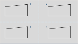
- If the trajectory is within the range of a laser, the laser is assigned sequential
trajectories as shown below:

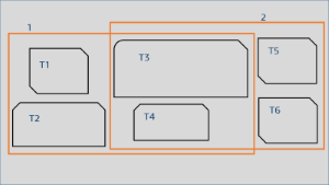
- If the trajectory is within the range of multiple lasers, the algorithm equally
distributes the total length of each trajectory assigned to the lasers. Each laser has a
balanced length of the trajectory. For example, the form T3 below is assigned to the
laser 2 because the total calculated distance of T5 plus T6 is less than the calculated
distance of T1 plus T2. To assure that both trajectories are as equal as possible, T3 is
assigned to laser 2 and T4 is assigned to laser 1.

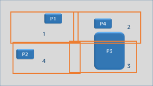
- If the trajectory falls outside the range of the lasers, the trajectory is split and
assigned to the lasers according to the trajectory length.

