About Probing Process Concepts | ||
| ||
The probing process is as follows:
Measure (Internal cylinder, rib width...) -> Process (Compare measure with predefined values) -> Action (Updates a compensation register (origin, cutter), Stop program (M00)
resulting in the following steps:
Definition of the parameters of the probing operation |  | Computation of the Tool Path
| | Simulation Video with collisions checking |
 | ||||
Definition of the user macro in PPTable file | | Generation of the APT file |
The tool path is simulated with the video tool to check the collisions between the tool and the part. No material is removed and the collision checking is not activated in probing feedrate.
It is impossible to define exactly all the probing cycles as each controller has its specific macro for the same cycle. Therefore, the probing operations is configured to your needs:
- for the strategy parameters: you can add parameters to the probing operation, in addition to the standard ones.
- for the format of the output APT file generated: the generated syntax is configurable in the your PPTable.
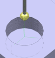
In the examples given in related files:
- feedrate for approach is displayed in pink,
- feedrate for probing is displayed in green,
- feedrate for retract is displayed in blue.