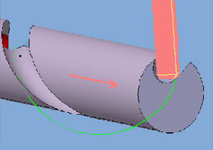
Sweep Helix Following | ||||
|
| |||
Machining Strategy Parameters
From the sensitive area, you can define the following strategy parameters:
- X offset.
- Y offset.
- Delta A.
- Direction of the start/end path.
Machining Parameters
- Tool path style
-
The options in the Tool path style list are as follows:
- Zig-zag: The tool path alternates directions during successive passes. .
- One-way: The tool path always has the same direction during successive passes and returns to the first point in each pass before moving on to the first point in the next pass.
- Machining tolerance
- Specifies the maximum allowed distance between the theoretical and computed tool path.
- Compensation
- Tool compensation with profile output in XY plane (G41,G42).
- Helix output
- Specifies the formal description output of the helix. The options
in the
Helix output combo box are as follows:
- Yes: Dedicated APT instruction output containing helix vectors.
- No: XYZ IJK APT output.
Radial Parameters
- Distance between paths
- Defines the maximum distance between two consecutive tool paths in a radial strategy.
- Number of paths
- Defines the maximum number of tool paths in a radial strategy.
Axial Parameters
- Distance between paths
- Defines the maximum distance between two consecutive tool paths in an axial strategy.
- Number of paths
- Defines the maximum number of tool paths in an axial strategy.
Finishing Parameters
- Mode
- The options in the
Mode combo box indicate whether or not
finish passes are generated on the sides and bottom of the area to machine.
The options are:
- No finish pass
- Axial finish pass
- Radial finish pass
- Axial finish thickness
- Specifies the thickness of material that is machined by the axial finish pass.
- Radial finish thickness
- Specifies the thickness of material that is machined by the radial finish pass.
Tool Axis
- Mode
- The options in the
Mode combo box are as follows:
- No milling lead
- Constant Lead
- Milling lead angle
- When a milling lead angle is applied, the tool axis in the tool
path is different from the axis defined in the helix sweep design feature.
Note: This may lead to inconsistency between the design and the manufactured product.
Geometry Parameters
From the sensitive area, you can define the following geometry:
- Part
- Sweep helix features (mandatory)
- Vector Table
-
The dynamic vector table displays information associated to the various vectors in a helix machining operation. You can define specific vectors for a linear helix or coefficients for a corner helix. You can use the vector table to define the feedrate reduction zone.
You can right-click on any vector in the vector table to:
- Insert or remove an interpolated vector.
- Set the extension or limitation of a linear axis (X, Y, or Z).
- Set the extension or limitation of a rotary axis (A or B).
- Analyze an interpolated vector or an extension/limitation in the 3D area.
Tools
Recommended tools for Sweep Helix Following are:
- End Mills
 .
.
- Conical Mills
 .
.
- T-Slotters
 .
.
Feedrates and Spindle Speed Parameters
- Feedrate
-
Available feedrate parameters are:
-
Feedrate:
- Approach
- Machining
- Retract
- Transition: Check the box to
activate transitions with the following options:
- Machining
- Approach
- Retract
- RAPID
- Local
For more information, see Setting a Transition Feedrate.
- Choice of
Unit:
- Linear: Length in feed per minute and unit is set to mm_mn.
- Angular: Length in revolutions per minute and unit is set to mm_turn.
-
Feedrate:
- Spindle Speed
- Check the box to activate the
Spindle output instruction in the generated
NC data file. If the check box is selected, the instruction is generated.
Otherwise, it is not generated.
- Machining spindle speed
- Choice of
Unit:
- Linear: Length in feed per minute and unit is set to mm_mn.
- Angular: Length in revolutions per minute and unit is set to mm_turn.
- Compute
- Feeds and speeds of the operation is updated according to tooling feeds and speeds by selecting the Compute button located in the Feeds and Speeds tab of the operation.
For more information, see About Feeds and Speeds.
Macro Parameters
You can define transition paths in your machining operations by means of NC macros:
- Approach: to approach the operation start point. The particular case of using a Circular horizontal axial approach macro for pocketing is described in Macros Parameters.
- Retract: to retract from the operation end point,
- Linking:
- To link two non consecutive paths
- To access finish and spring passes.
- Return to Finish Pass to go to the finish pass
- Clearance to avoid a fixture, for example.
The proposed macro modes for Approach and Retract macro are:
- None
- Build by user
- Horizontal horizontal axial
- Axial
- Ramping
The proposed macro modes for Clearance macro are:
- Distance
- To a Plane
- To safety plane
For more information, see Defining Macros.