4X Pocketing Evolutions | ||||
|
| |||
Capability to manage any revolve surface as bottom of pocket
Select any kind of revolve surface and not only cylindrical or conical surface, as the behaviour is the same.
The surface types are:
- CATCylinder
- CATSphere
- CATCone
- CATTorus
- CATRevolutionSurfaceType
- CATChamferSurface
- CATCircularSweep
- CATDraftSurface
- CATFilletSurface
- CATOffsetSurface
- CATSweepSegmentSurface
- CATNurbsSurface are not managed even if it represents a revolution surface.
Here is a example with a CATTorus surface: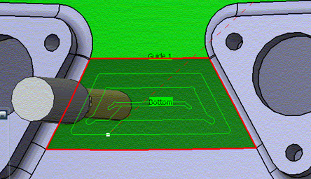
Select and manage several continuous faces to define the machining side
The selection of several continuous faces can define the bottom of the pocket. The automatic contour detection takes into account the set of selected faces, as the behaviour is the same as for one face.

When defining the machining side for one of the selected faces, the machining side is automatically defined for all the adjacent faces. This input is not compulsory and the system computes the machining side based on the bottom selected.

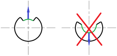
There is the option to specify the machining side by selecting the surface and verify the side in the work area. If not the one expected, then invert.
Management of a Closed Surface of 360 degrees and Cutting Point
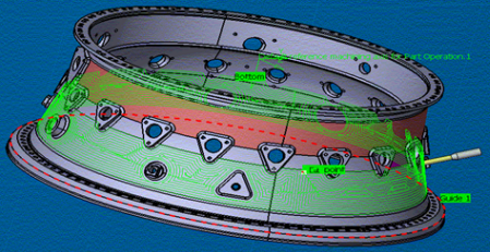
A set of surfaces of 360 degrees is defined as the bottom surface. An optional Cutting Point is defined by you (similar to the definition of a Start Point). This Cutting Point must lay near one contour of the 360 degree surface.
- If the Cutting Point is defined, the surface is cut by a polyline passing through the cutting point; in many cases, the polyline is a straight line but it can include a sharp edge depending on the geometry complexity; the cutting point is ignored if the cutting point is defined near an island. The guide contour of the bottom must include 2 external boundaries which are the natural boundaries of the selected surfaces. This cutting operation allows replacing these natural external boundaries in a single external boundary.
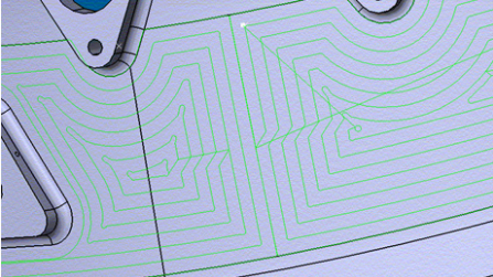
- If no Cutting Point is defined, it is necessary to select 2 external boundaries:
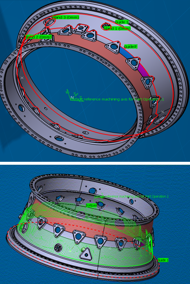
For surfaces of 360 degrees and for revolve surfaces (except cylinder and cone), it is not allowed to position the tool tip outside of the bottom surface. Therefore, overhang greater than 50% or a negative offset on the contour are forced respectively to 50% and 0.
Automatic Collision Detection between the Tool Assembly and the walls of the Pocket and the walls of islands
If the part is defined in the Part Operation, the collisions between the tool assembly (tool holder and tool shank) and the part is detected and solved automatically by modifying the tool axis lead angle or by creating linking motions. If the collisions cannot be solved, the tool path computation fails with a warning message.