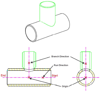
- Case 1. Branch
- The positioning points defined in UDF for branch cases are Origin,
Branch Direction, and Run Direction. The
UDF origin locates on the point, Origin below which is an
intersection point of branch and run pipe. Other directions align with the points as
below.
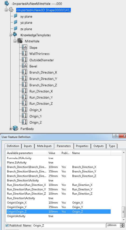
- To specify the directions, below key names using for published parameters. This represents the
points of origin, branch, and run direction.
- 1 - Origin: Origin_X, Origin_Y, Origin_Z
- 2 - Run Direction: Run_Direction_X, Run_Direction_Y, Run_Direction_Z
- 3 - Branch Direction: Branch_Direction_Z, Branch_Direction_Z,
Branch_Direction_Z
- 4 - Start
- 5 - End


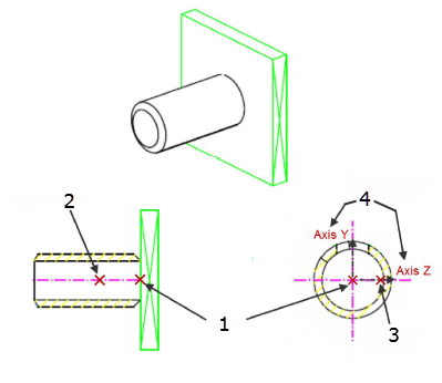
- Case 2. Pipe/Piping parts
- The positioning points defined in UDF for branch cases are
Origin, Pipe Direction, and
Orthogonal Direction. The UDF origin locates on the point
Start or End, and others align with the
points as below.
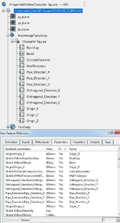
- Defining the Root Gap parameter. This value creates the
Root Gap feature to apply the value on the cutting
feature.
- To specify the directions, below key names using for published parameters. This
represents the points of origin, branch, and run direction.
- 1 - Origin: Origin_X, Origin_Y, Origin_Z
- 2 - Pipe Direction: Pipe_Direction_X, Pipe_Direction_Y, Pipe_Direction_Z
- 3 - Orthogonal Direction: Orthogonal_Direction_Z, Orthogonal_Direction_Z,
Orthogonal_Direction_Z
- 4 - Pointed Axis of Publication


|


