General
- Trajectory Name
-
Displays the default name of the new trajectory. You can edit this name.
- Tool Name
-
The tool attached to the selected robot. If a manufacturing cell is selected, this field is empty and you can pick a tool by clicking Add/Change Tool
 . .
- Geometries
- The number of selected surfaces. Click
 to add or remove surfaces. to add or remove surfaces.
Path tab- Strategy
- Specifies the strategy in which strokes are sequenced.
- Zigzag
- When selected, the alternate strokes in the path are in the opposite direction.
- One-way
- When selected, all strokes in the path are in the same direction.
- Via Pattern
- Sets the connection between last the depart point of a stroke to the first approach point of the next stroke.
- Arc
- When selected, the approach point and depart point of two consecutive strokes are connected with an arc. The third point for the arc is created from Via offset value.
- Line
- When selected, the approach point and depart point of two strokes are connected with a line.
- Via offset
- The distance from the depart point in the depart direction. It is used to create the third point for the arc connecting the approach point and depart point of the two consecutive strokes.
- Distance between strokes
- Constant
- When selected, all strokes in the path have same constant distance between each other.
- Distance
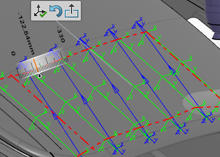
- Specifies the distance between two strokes. The distance between passes is also shown in the work area. This value can also be edited using the manipulator attached to the blue lines associated to Overlap distance.
- Variable
- Each stroke can have a different distance specified from the previous stroke. When selected, you can select a stroke (either from the Stroke tab or by selecting a stroke in the work area) and set the distance from the Stroke tab or by dragging the blue line in the work area.
- Path parameters
- Stroke Tolerance
- Set the sag value. The uniformity of the tags on the strokes is determined by this value.
- Skip Holes Larger Than
- You can skip holes in the geometry during path generation if a given hole size is greater than this value.
 By default, this option is disabled. By default, this option is disabled.
- Path Extremities
- Select to add first Start Point and last End Point to the path. The distance of these points can be modified by dragging the solid blue lines in the work area.
- Reposition
- Creates a red boundary box around the surface sequence.

You can click and drag the lines of the boundary box to lengthen/shorten the strokes of the trajectory, or increase/decrease the size of the trajectory, therefore increasing or decreasing the number of strokes. Click Exit to exit the sequence reposition state. - List of points
- When clicked, displays all of the points in the path. Selecting a point in this panel (or selecting a tag in the work area) moves the tool and robot to that point (if reachable), places the orientation Robot at that location and displays a context toolbar.
- Approach Retract Templates
Stroke tab- Selected Stroke
- If Distance between stroke is Constant, Selected Stroke is set to All and no stroke can be selected (changes in this tab apply to all strokes). If Distance between stroke is Variable, any stroke can be selected from List of points. Strokes can either be selected from the work area or from the list.
- Define Offsets
- Distance from Previous Stroke
- Specifies the distance between the selected stroke and the previous stroke. This distance can also be modified using the orientation Robot.
- Number of Approach Points
- Applies to only a selected stroke. The approach point position can be modified using the orientation Robot.
- Number of Retract Points
- Applies to only a selected stroke. The retract point position can be modified using the orientation Robot
- List of points
- Displays the list of points contained in the path.
|
 .
. to add or remove surfaces.
 By default, this option is disabled.