Defining Pathways without Footprint

You can generate an automatic guided vehicles (AGV) or worker pathway without specifying its footprint with the Generate Path System command. It can be done directly in the 3D view or automatically by importing an Excel file. Once the pathway is created, you can modify it.

This task shows you how to:


Before you begin: Open a scenario with an assembly line that includes workers or AGVs completing tasks.

Generate a Path System

  1. In the Setup section of the action bar, click Generate Path System and 
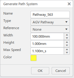
select a parent or pathway.
    The Generate Path System panel displays.

  2. Define the pathway's attributes:

    • Name
    • Type can be defined as either:
      • AGV Pathway
      • Worker Pathway
    • Reference can be defined as either:
      • None: to manually select the section's points in the 3D view
      • File based: to import the section information from an Excel file
    • Width
    • Height
    • Max Speed
    • Color.

  3. Click OK.
    If Reference is set to None, the 3D view displays. If it is set to File Based, a file browser displays.

Pathway Creation: File Based

If Reference is defined as File Based, select the appropriate Excel file in the file browser.
The pathway is automatically generated.

You can modify it. For more information, see Modify the Pathway.

Pathway Creation: Manual

  1. If Reference is defined as None, the 3D view displays.
  2. In the 3D view, select a 3D axis or a start point on the floor.
    A black line displays a preview of the section. It turns blue when it is aligned with an X or Y axis.
  3. Create a segment by selecting one of the following segment types in the bubble bar:

    • Straight : when selected, a linear segment is created. You can edit its length with the ruler or the handle:
      • You can modify the ruler's value by dragging the ruler handle or double-clicking and editing the value in the editor.
      • You can modify the segment end's elevation by dragging the Z handle.
    • Three point curve : select an end point and a third point on the curve. You can edit the arc's radius and angle with handles.
    • Right curve : when clicked in the bubble bar, a default right curve with a 1000 mm radius and a 90 degrees angle is created. You can edit the arc's radius and angle with handles.
    • Left curve : when clicked in the bubble bar, a default left curve with a 1000 mm radius and a 90 degrees angle is created. You can edit the arc's radius and angle with handles.

  4. In the 3D view, select or input a second point to define a path section. You can use the direction of the last created section as a reference to create a parallel, perpendicular, or tangent section.
    A green line displays as the last section's reference direction. It turns blue when it is aligned parallel or perpendicular to the reference direction.

    Click .

  5. Optional: Repeat the previous steps if required.
  6. Optional: You can delete the last created section. Click in the bubble bar.
    The last created section is deleted. Click .
  7. When all the required path sections are created, click .
    The pathway is created.

Modify the Pathway

Once the pathway is created, commands in the bubble bar let you modify its sections (edit them, change their types), delete sections from it, or add branches on junctions.

  1. You can edit sections of the curved or straight type with at least one free side:

    1. Click .
    2. Select a section.
    3. If a curved section is selected, you can recreate its curve with two fixed ends, select a third point, and modify the radius and angle.
    4. If a straight section type is selected, to define its end point, you can either extend its free side or select a point.
    5. Click .

  2. You can change a section's type from straight to curved and vice versa:

    1. Click .
    2. Select any section of the straight or curved type.
    3. If a curved section is selected, it turns straight with the same end points.
    4. If a straight section is selected, a curved section is created with the same end points. A third point can be selected, and the radius and angle can be modified.
    5. Click .

  3. You can delete one or more sections from the pathway:

    1. Click .
    2. Select a section.
    3. If the section is connected by down stream sections, a message displays: click Yes.

    The section is deleted. Click .
  4. You can add branches at junctions of the segments or on specific segments:
    1. Click .
    2. Select a junction point or a point on a section and click .

      Note: If a point on a section is selected, the section is broken at that point, and that point becomes a junction to create a branch.

    3. Select a section type to create a branch from that point.
    The branch is created. Click .