About Machining Features for Milling Machining

Below are some concepts about machining features used in Milling Machining.

This page discusses:

Machining/Slope Areas

Machining areas are used to define different zones on a part: First you define the machining areas and then you assign a machining operation to each of them. This is an useful approach if, before you start machining, you are aware that the part has areas that will require different types of machining operation. Another feature of machining areas is their ability to be divided into horizontal, vertical and sloping areas and have a machining operation assigned to these areas.

A machining area can be:

  • The whole part (for example, in roughing).
  • A subset of the faces on the part.
  • A subset of faces on the part with a limiting contour.

Limiting contours are not taken into account to compute the slope areas. However, they will be taken into account while computing tool paths on those slope areas:

  • When you create a slope area, you associate one machining operation to each subset.
  • The corresponding tool path is limited first by the defined subset and then by the limiting contour defined in the Machining/Slope Area Geometry tab page.

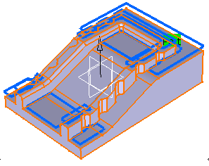
Horizontal and intermediate areas are defined as being inside the lines, whereas vertical areas are defined as being outside the lines, e.g.:

  • Only vertical areas are shown, they are the areas not inside the closed red contours:

  • Only horizontal areas are shown, they are the areas inside the blue closed contours:
Rework Areas

Once you have machined a part and visually checked it, you may decide to rework certain areas where residual material remains. Defining a rework area allows you to focus only on those areas, resulting in a gain of time.

Rework areas defined on a given part can be re-used on another part, with the following limitations:

  • This re-usability is possible with a design change (i.e. evolution of the part) but not with a completely different part (from punch to die, for example).
  • Re-usability is more uncertain if many manual divisions and/or transfers to other subsets have been carried out: The computation of the rework area takes those cutting points and subsets into account, although they are no longer relevant if the part has changed dramatically, leading to incoherent results (horizontal areas seen as vertical, for example).
  • Those manual divisions and subsets can be removed from the original rework area using Remove Cutting Points and Delete Non-updated Subsets. The original rework area can then be re-used on another part, provided the part is only an evolution from the original one.

Offset Groups

Offset groups can be used to machine upper and lower dies using a single set of geometry.

Offset Groups in Operations

You can select an offset group in a machining operation.

  • An offset group can contain one or more offset areas.
  • You can apply an overall offset to an offset group.
  • An offset area is a group of faces (at least one) with an offset value (with respect to the original part) and a color to identify it.

By default,

  • The offset group selected in the previous machining operation is always proposed at the creation of a new machining operation.
  • The last created offset group is proposed for the first machining operation of a Manufacturing Program.

When you modify a machining operation and change the reference offset group, the others machining operations will not take this modification into account.

This behavior is independent of option Use default values of the current program defined in the Me > Preferences > Machining > Operation tab.

Offset Global versus Offset Local

Below are listed the differences between a global and a local offset.

Offset Global in the upper part of the dialog box is the overall offset that will be applied to the group in general. However, it is applied only to offset areas in the offset group that do not have their own specific offset.

Offset Local in the Create tab is a local offset applied to specific areas.

For example, let's consider a group with:

  • An area that has a specific offset (Offset Local in the Create tab) of 10 mm and
  • The remaining area that has no offset assigned to it (this is its original status).

Apply an overall offset (Offset Global) of 5 mm to this group:

  • The first area keeps its specific offset of 10 mm,
  • Whereas the 5 mm overall offset is applied to the second area.

When you define a local offset on a part that is the output of assembly operations (Add, Remove, Assembly), do not select that part in the PPR tree, but select all the faces of this part in the work area.

Notes:
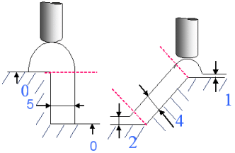
  • The thickness of the offset can be negative. If you want to use a negative value, the tool corner radius must be greater than the absolute value of the offset.
  • In the transition between faces with 2 different offsets, only the bigger offset is taken into account.

  • Offset groups can be used with all machining operations and rework areas. If you are using a rework area that includes an offset group in a machining operation, you will not be able to modify the offset group.
  • The same face cannot be used in two separate offset areas in the same group. To create two different offsets on any given face, create a new group for the second value.
  • If an offset is defined in the dialog box of the machining operation, this offset is added to the Offset Global of the offset group.

In our example above:

  • On the first area, you will have the 10 mm Offset Local + the offset defined in the machining operation,
  • On the second area, you will have the 5 mm Offset Global + the offset defined in the machining operation.