3/5-Axis Converter Availability
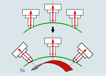
Since the post-processor is able to process 5-axis tool paths, the
3/5-Axis Converter is a process that can be included in the
computation of the tool path to convert a 3-axis machining operation into a 5-axis one. The computed tool path avoids collisions and takes machine
kinematics constraints into account.
More... opens the 3/5-Axis Converter
dialog box that contains:
- Machining strategy tab
 with: with:
- Global Modification
tab: Modify the tool axis of a tool path resulting from a machining operation without changing its contact point either by changing a 3-axis
tool path into a 5-axis tool path or by modifying a 5-axis tool
path,
- Collisions Checking
tab: Avoid collisions of the tool or the tool assembly within a 5
axis machining strategy. Collision checking is performed with the
selected geometry, not with the rough stock remaining from the
previous machining operation.
- Machine Kinematics
tab: Take those constraints into account.
- Macro tab
 . .
The check box to start the 3/5-Axis Converter is available at
the bottom of the Strategy
tab
for the following commands:
- Roughing, with End Mill tools (spherical only).
- Sweeping, with End Mill tools (spherical and
torical), and Lens Mill tools.
- Advanced Finishing, with End Mill tools (spherical
and torical).
- Pencil, with End Mill tools (spherical only).
- ZLevel, with End Mill tools (spherical and torical),
Barrel Mill tools, TSlotter and Lollipops (TSlotter with spherical shape).
- Contour-driven, with End Mill tools (spherical and
torical), and Lens Mill tools.
- Spiral Milling, with End Mill tools (spherical and
torical), and Lens Mills tools.
- Isoparametric Machining, with End Mill tools
(spherical and torical).
- Profile Contouring with End Mill tools (spherical
only), and Lollipops (TSlotter with spherical shape).
Note:
Conical tools are not available.
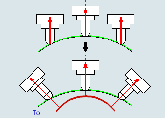
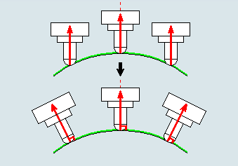
Global Modification
When selected, the Activate global modification check box
replaces all the tool axes of the tool path with the one selected in the Tool
axis mode list.
By default, Activate global modification is not selected.
The upper part of the graphic zone of the dialog box represents the initial tool path
whereas the lower part represents the modified tool path.
Tool axis mode lets you
select a new tool axis mode from the list. Notes:
- When Rolling is selected, the
Macro tab in the 3/5 axis converter is
deactivated (Macros defined in the ZLevel operation apply).
- For other tool axis modes, the Macro tab is
displayed. The macro defined in the operation (active by default) can be
applied.
Fixed Axis
The tool axis arrow proposes a context menu:
- Select defines the tool axis.
- Analyze starts the Geometry
Analyzer.
Thru a Point
The tool axis passes through a specified point.
- The label is a toggle to orient the tool axis To
the point or From the point.
- The point in the sensitive icon lets you select a point in the work area.
Thru a Guide
The tool orientation is controlled by a geometrical curve (guide), that must
be continuous. An open guide can be extrapolated at its extremities.
- The label is a toggle to orient the tool axis To
the guide or From the guide.
- The red curve in the sensitive icon lets you select a curve in the work area.
- Angle lets you specify a lead angle.
Normal to Part
The tool axis is normal to the part.
Angle lets you specify a possible frontal angle between
the tool axis and the normal to the part.
Fixed Angle
The new tool axis forms an angle with the initial tool axis.
- Angle
lets you specify this fixed angle.
- Privileged angle with the
tool path defines the angle a plane defined by the
direction of motion (Frontal angle) or in a plane
normal to the direction of motion (Lateral
angle).
Normal to Drive Surface
The new tool axis is normal to the drive surface.
Angle lets you specify a possible lead angle.
Note:
Use a smooth surface as the drive surface.
4 Axis
Converts a 3 axis or 5 axis tool path as follows:
Rolling (with Barrel tool only)
Only Barrel Milling tools are supported.
For each cutting point, the Rolling (with Barrel tool only) tool axis
mode positions the tool on the contact point position. Milling with the large
radius provides a good quality and increases the distance between passes, thus
reducing the machining time.
Associated parameters are:
- Max discretization angle to control the tool axis
variation along complex geometry. It is used to add more tool positions
(points and axis) if value is exceeded.
- Max tilt angle: Controls the tool tilt when the
slope angle of the wall decreases.
- Contact point position: Specifies the initial
contact point position, defined as a ratio of the barrel arc length.
- Contact: Defines the contact position option to
avoid collisions in undercut areas..
- Tilt Side: Defines the tilt side of the tool
according to the tangent motion and the initial tool axis.
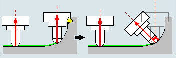
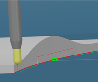
Collisions Checking
Clear the check box Activate collisions checking if you do
not want to perform a collision checking.
By default, the collision checking is active.
The left part of the graphic zone in the dialog box represents the initial tool path
whereas the right part represents the modified tool path that avoids collisions.
You can perform the collisions checking on:
- The Part.
- The Check.
- The Design Part of the Part Operation. In that case, make sure that you have selected a valid Design
Part in the Part Operation.
By default:
- Part is selected.
- Check is selected.
- Design Part is not selected.
Note:
In a Profile contouring operation, you cannot select a
part. Select the Design Part (PO) check box and make sure
it exists in the Part Operation.
Tool axis mode lets you select a new tool axis mode from the
list. It is applied to the points in collision found.
None
The tool axis is not modified, the tool path stops before the collision
point, and the corresponding portion of tool path is removed.
Automatic
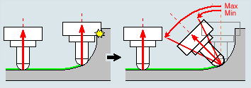
The tool axis is automatically computed to avoid collisions.
Normal to Drive Surface
Note:
Use a smooth surface as the drive surface.
More
More... gives you access to more parameters for the above
tool axis modes:
- For all tool axis modes except None:
- Max discretization angle specifies the
maximum angular change of tool axis between tool positions. It
is used to add more tool positions (points and axis) if value is
exceeded.
- Minimum
length specifies the minimum distance that must
exist between two collision points to allow the modification of
the tool axis between those two points.
- For the tool axis mode Normal to part,
Angle lets you specify a possible angle
between the tool axis and the normal to the part.
- For the tool axis mode Fixed angle:
- Angle lets you specify the fixed angle.
- Privileged angle with the tool path
defines the angle a plane defined by the direction of motion
(Frontal angle) or in a plane normal
to the direction of motion (Lateral
angle).
- For the tool axis mode Automatic:
- Minimum angle and Maximum
angle define the range within which the tool
axis can vary.
- Step angle defines the computation step
used to find the optimal angle to avoid collisions. The smaller
the Step angle, the longer the
computation time.
- For the collisions checking strategy Automatic and the tool axis
mode Rolling (with barrel tool only):
- Contact point position range specifies
the range of the contact points. It is defined as a ratio of the
barrel arc length, centered on the initial contact point
position.
- Contact up to tool tip allows the contact
up to the tool tip when a collision is found. If selected,
Contact point position range is not
editable anymore.
Offset on tool defines
the offset applied on the tool to avoid collisions.
Offset on assembly
defines the offset applied on the tool assembly to avoid collisions.
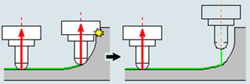
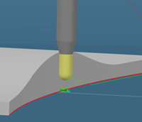
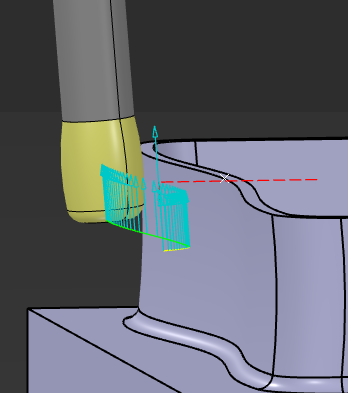
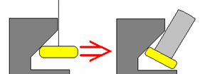
Undercut Milling is available only for a
ZLevel operation with a TSlotter tool or Barrel
Milling tool, and if Collision Checking is activated.
By default, Undercut Milling is not selected.
The ZLevel operation takes the tool body into account to
compute the tool path.
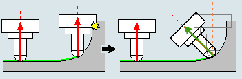
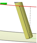
In
the image above, the tool with its body cannot machine more material: The tool
body is in collision. Undercut Milling computes the tool path with a quasi-null
tool body.
Undercut Milling + 3To5-Axis Converter.
Machine Kinematics
This tab lets
you correct problems encountered with respect of the machine kinematics.
By default, Optimize rotary
DOF,Correct out of limit points, and
Correct large angular variation on rotary DOF are not
selected.
Notes:
- If problems subsist after computing the tool path with those options, a
message is displayed.
- These corrections apply to the tool path of the current machining operation.
- The machine configuration on the first point of the current machining operation is seen as the result of a motion from the Home position to this first
point. Thus, it may differ from the actual one, resulting from previous machining operation and machine instructions.
- Angular variations between two points cannot be detected on the first point
of the tool path, because the position of the machine before this point is
unknown.
Optimize Rotary DOF
This check box is available if:
- The check box Activate global modification in the
Global modification
tab is not selected,
- The Tool axis mode in the Collisions
checking
tab is defined as Automatic.
Optimize rotary DOF:
- Supports only MTB milling machines,
- Does not support Mill-Turn or generic machines,
- Does not support interchangeable heads.
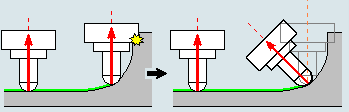
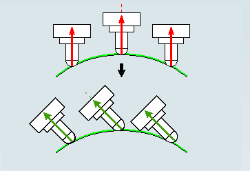
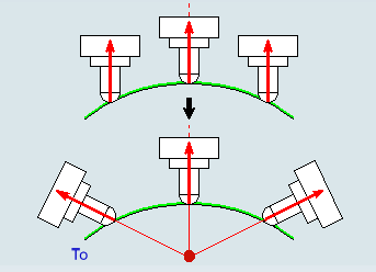
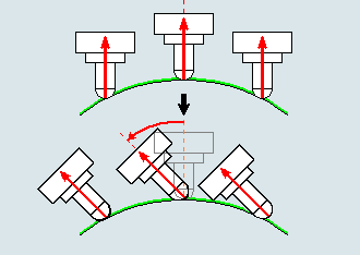
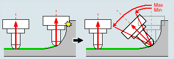
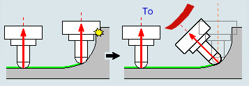
When selected, Optimize rotary DOF minimizes the
variations of rotary degree of freedom, as well as the tool axis variations:
- On each detected collision point, the 3/5-axis converter may generate a
tool axis variation to avoid the collision.
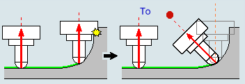
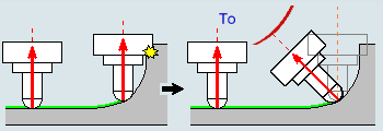
- To avoid a collision, the original 3-axis tool path is temporarily
converted to a 5-axis tool path. It then reverts to 3-axis, before being
converted again to 5-axis as shown in the image below. The variation
shown in the middle image is not useful.
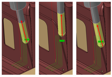
- When selected, Optimize rotary DOF avoids those
tool axis variations:
- The machine does not have to slow down to cope with the tool
axis variations,
- The machine output is of better quality since the machine has a
linear and constant behavior.
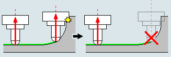
Correct Out of Limit Points
When this check box is selected, the points out of limits are removed:
- If the point is out of limits in the X, Y or Z-Axis, it is removed.
- If the point is out of limits in the A, B, or C-axis, the tool axis is
corrected and locked in the position limit.
- If the point with the corrected axis is in collision, the point is
removed.
Correct Large Angular Variation on Rotary DOF
If between two points of the tool path, the
variation on a rotary DOF (angular join of the machine) exceeds the
Maximum variation, you can select one or several
check boxes to modify the machine configuration. When you select several check
boxes, the most appropriate one is applied to any given point.
- Linking macro:
The modification is done within the existing linking macro of the tool
path.
- Tool pass: When
the tool is in contact with the part, you can define a
Fanning Distance.
Note:
Entering 0mm deactivates the
Fanning Distance.
- Retract macro: A
retract pass is added to reconfigure the machine.
In
addition, you can define the Maximum discretization on
the rotary DOF: If an angular variation between Maximum
variation and Maximum discretization is
detected between two points, new points are added to the tool path.
The status of the Machine Kinematics checking is displayed
in the Activities Process Tree, in a dedicated column.
Path Closed with Macros
When collision points found on the tool path are removed, the tool path must be
closed. This tab lets
you do that with Approach, Retract, and
Clearance macros.
|