- From the Surface Machining section of the action bar, click Contour-driven
 . .
A Contour-driven entity is added to the manufacturing program.
The Contour-driven dialog box opens at the Geometry tab
 .
-
Still in the Geometry tab:
- Click the red area in the sensitive icon and select the part in the work area.
- Double-click anywhere in the work area to confirm your selection and redisplay the dialog box.
-
Select the Radial tab and set the Stepover as required, e.g. Constant 2D.
-
Select the Machining Strategy tab
 and select Between contours. and select Between contours.
-
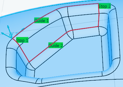
In the sensitive icon:
-
Click Guide 1.
-
Select contours in the work area.
- Repeat this step with Guide 2, then Stop 1
and Stop 2 to obtain a contour like that:
- Select the Tool tab
 to choose a tool. to choose a tool. -
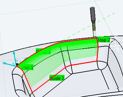
Click Display or
Simulate to check the validity of the machining operation.
- The part is machined between two guide contours delimited at either end by two others.
- A progress indicator is displayed.
- You can cancel the tool path computation at any moment before 100% completion.
- Click OK in the Display or
Simulate dialog box, and again in the main dialog box to create the machining operation.
The tool path is created.
|