-
From the Surface Machining section of the action bar, click Contour-driven
 . .
A Contour-driven entity is added to the manufacturing program.
The Contour-driven dialog box opens at the Geometry tab
 :
-
Still in the Geometry tab:
- Right-click the red area of the icon,
- Select a part,
- Click OK in the Face Wizard to confirm your
selection and redisplay the dialog box.
-
Go to the Machining Strategy tab
 and select Between contours. and select Between contours.
-
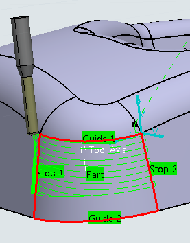
Go to the Radial tab:
- Select Constant 3D as the stepover strategy.
- Select the guides and stops.
Note:
According to the stepover selected, stops will be requested or not.
-
If necessary, set the distance between paths.
- As a Sweeping Strategy, select From guide 2 to guide 1
- Go to the Tool tab
 to select a tool. to select a tool. -
Click Display or
Simulate to check the validity of the machining operation.
The result is of an equal distance on the part surface from guide 2 to guide 1.
Note:
The bottom of the machined area and how the paths remain perfectly parallel to each
other but because of the shape of the surface they finish gradually on Guide 1.
-
With the same parameters, switch to Maximum 3D and click Display or
Simulate.
There is a variation in the distance between the paths on the surface but the paths
respect both guide 1 and guide 2. There is no gradual finish on Guide 1 as there was with
Constant 3D. 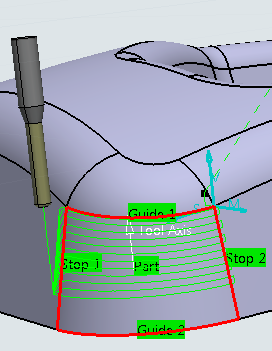
|
