Creating an Isoparametric Machining Operation with Interpolation | ||||
|
| |||
- From the Surface Machining section of the action bar, click Isoparametric Machining
 .An Isoparametric Machining entity is added to the manufacturing program. The dialog box opens at the Geometry tab
 .
.
-
Go to the Strategy tab
 to specify parameters for:
- Machining, e.g.:
- Tool path style: Zig zag
- Machining tolerance: 0.01mm
- Max discretization step: 10000mm
- Max discretization angle: 180deg
- Radial, e.g.:
- Stepover: Scallop height
- Scallop height: 0.1mm
- Skip path: None
- Start extension: 0mm
- End extension: 0mm
- Tool Axis, e.g.:
- Tool axis mode: Interpolation
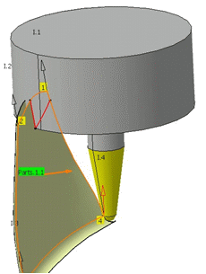
A default reference tool axis (A) is displayed. Double-click these axes to modify them. - Machining, e.g.:
- In some cases, such as the machining of turbine blades, you need to
avoid collisions and have a perfect fluidity of the tool
trajectory.
To achieve this, you can define additional interpolation axes on the part to machine,
- Click one of the red interpolation axes in the sensitive icon.
An interpolation axis (I) appears at each of the corners of the surface to be machined. The Interpolation Axes dialog box is displayed. All the interpolation vectors are listed with their position, direction and status.
- Click
 to add an interpolation vector.
The Interpolation Axes dialog box disappears.
to add an interpolation vector.
The Interpolation Axes dialog box disappears. - Pick in the work area to indicate the position of this new interpolation vector.Its axis definition dialog box appears (it is described below).
- Click OK in the dialog boxes when you are done.
- Pick a vector in the dialog box. It is highlighted in the work area.
- Click
 to remove the interpolation vector
selected in the dialog box.
to remove the interpolation vector
selected in the dialog box.
- Click
 to edit the interpolation vector selected
in the dialog box. The axis definition dialog box is displayed.Note: When the Angles option is selected, the list proposes by default an item specific to interpolation axes: Lead (Angle1) & Tilt (Angle 2). Key in those values in the Angle 1 and Angle 2 fields below.
to edit the interpolation vector selected
in the dialog box. The axis definition dialog box is displayed.Note: When the Angles option is selected, the list proposes by default an item specific to interpolation axes: Lead (Angle1) & Tilt (Angle 2). Key in those values in the Angle 1 and Angle 2 fields below. - In both modes, select the Display tool check box to
display the tool in its real position.
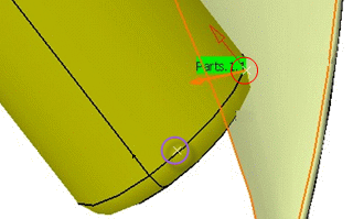
- The purple circle shows the computed tool tip point
- The red circle and the red arrow show the tool contact point and axis position.
Note: Check Interferences will not become available if the machining operation parameters are not coherent.If you select a point that does not belong to a selected face, the point is projected to the nearest select face.
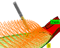
- Click it to start checking
those interferences.
-
They are checked between the complete tool assembly and the part
and check if any.
- If no interferences are found, the light on the left turns green.
- If interferences are found it turns red. They are displayed in red by the intersection of the tool with the surface in collision.
-
They are checked between the complete tool assembly and the part
and check if any.
- Click one of the red interpolation axes in the sensitive icon.
- Go to the Tool tab
 to select a tool.
 - Go to the Feeds and Speeds tab
 to specify the feedrates and spindle speeds for the machining operation.
- Go to the Macros tab
 to specify the machining operation transition paths (approach
and retract motion, for example).
to specify the machining operation transition paths (approach
and retract motion, for example).
-
Click Display or
Simulate to check the validity of the machining operation.
- The tool path is computed.
- A progress indicator is displayed.
- You can cancel the tool path computation at any moment before 100% completion.
- Without an additional interpolation axis:
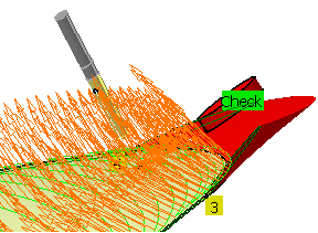
- With an additional interpolation axis: