- From the Surface Machining section of the action bar, click Isoparametric Machining
 . .
An Isoparametric Machining entity is added to
the manufacturing program.
The dialog box opens at the Geometry tab
 :
-
Still in the Geometry tab, define the geometry:
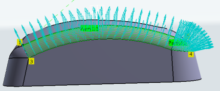
- Click the red part surface in the icon then select the desired surfaces in the work area.
The Face Wizard appears to help you select faces or belts of faces. These can be adjacent or non-adjacent. - Click a red point in the icon then select the four corner points of the selected surfaces.
Machining starts from point 1 to point 2, and finishes either from point 3 to 4 or 4 to 3 (depending on the One way or Zig zag tool path style).
-
Go to the Strategy tab
 to specify parameters for:
- Machining, e.g.:
- Tool path style: Zig zag
- Machining tolerance: 0.01mm
- Max discretization step: 10000mm
- Max discretization angle: 180deg
- Radial, e.g.:
- Stepover: Scallop height
- Scallop height: 0.1mm
- Skip path: None
- Start extension: 0mm
- End extension: 0mm
- Tool Axis, e.g.:
- Tool axis mode: Lead and tilt
- Guidance: Fixed lead and tilt
- Lead angle: 0deg
- Tilt angle: 0deg
- Click Preview in the dialog box to verify the parameters
that you have specified.
A message box appears giving feedback
about this verification.
- Go to the Tool tab
 to select a tool. to select a tool. - Go to the Feeds and Speeds tab
 to specify the feedrates and spindle speeds for the machining operation. to specify the feedrates and spindle speeds for the machining operation.
- Go to the Macros tab
 to specify the machining operation transition paths (approach
and retract motion, for example). to specify the machining operation transition paths (approach
and retract motion, for example).
-
Click Display or
Simulate to check the validity of the machining operation.
- The tool path is computed.
- A progress indicator is displayed.
- You can cancel the tool path computation at any moment before 100% completion.
- Click OK in the Display or
Simulate dialog box, and again in the main dialog box to create the machining operation.
The tool path is created.
|