Analyzing and Updating Welds from Results | |||
| |||
-
Click Simulate and Generate Results
 .
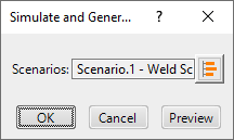
The Simulate and Generate Results dialog box appears.
-
Click OK in the Simulate and Generate
Results dialog box.
The current scenario is executed and the progress of the simulation is displayed in the progress bar. You can stop the simulation anytime by clicking Cancel.
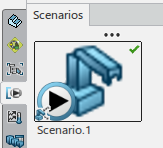
Once the simulation is complete, new results corresponding to the specification are created under the Scenarios side tab.
-
In the Analysis & Output section of the action bar, click Analyze Results
 to view the results of the analysis.
The Analyze Results dialog box appears.
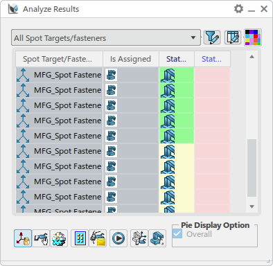
The fasteners that were selected for analysis are listed in the Spot Target/Fastener column of the table. The list of fasteners displayed in this column can be filtered by their assigned and feasibility state:

For welds that are GeoSpot welds, an Is Geo column indicate the welds that are GeoSpot welds. Note that the Is Geo column does not appear when using resource-centric data.

Welds that are assigned to any robot in the current scenario are indicated as shown above in the Is Assigned column. A yellow icon indicates that a weld is assigned to any other robot that is included in the current scenario.
Each subsequent column represents a weld gun that was selected for analysis. If Compute with Tool flipped is selected in the Tool Search Scenario dialog box, an additional column is also provided for each weld gun in its flipped state.
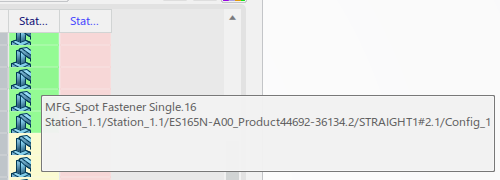
Hold the mouse cursor over a cell to see the full name of the fastener for that cell. After a moment, the full name of the tool also appears.
Each cell is color-coded to represent the feasibility of each selected gun with each fastener. By default:
 indicates that the target is reachable and requires no
modification with the current tool.
 indicates that the target is fixable and can be used with the
current tool by modifying the target orientation.
  indicates that the target is unfixable, where the current tool is
not valid with any orientation of the fastener.
Default colors can be changed by clicking Customize Cell Colors
 and clicking the color swatch in the Panel Color
dialog box.
The Analyze Results dialog box also provides the following commands:

Lock/Unlock Translation switches the lock or unlock status of the translation of selected welds. 
Snap/Unsnap Tool switches whether the tool is snapped to the selected weld. 
Make Product Translucent determines the product translucency. This can help when the reach disc appears obstructed by the product. 
Section Preferences provides options to define the section plane when performing sectioning at the weld location. 
Save Section Result saves the section result in a representation of the given name. 
Launch Simulation start a partial simulation. 
Auto Assign Welds to Resources assigns welds to robots based on the reach status, such that they are evenly distributed among the robots used in the analysis. When Assign Nearest is selected, welds are assigned to a robot based on reach status and proximity to the weld. 
Resource Utilization Time verifies the status of resource utilization. -
In the Analyze Results dialog box, click a colored cell.
The robot snaps to the selected target and the Analysis disc appears.
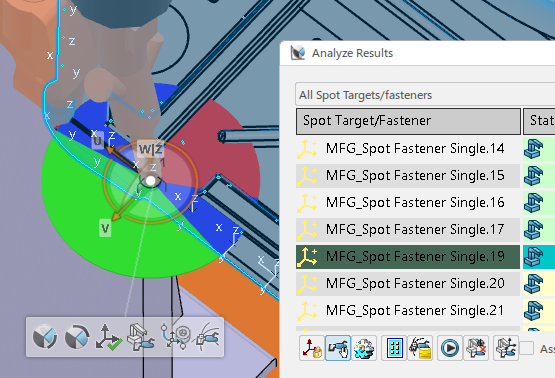
A context toolbar also appears, and provides the following commands:

RotateX Closest rotates the gun to the center of the closest green zone (reachable zone). 
RotateX Biggest rotates the gun to the center of the biggest green zone (reachable zone) when there are multiple green zones. 
Commit Position saves a modified manufacturing weld location. 
Assign Resource allows you to assign a resource to an unassigned fastener. 
Reset to Last Committed returns a modified orientation to the last committed position. 
Generate Section displays a 2D sectional view of the current position in the Sectional View dialog box. -
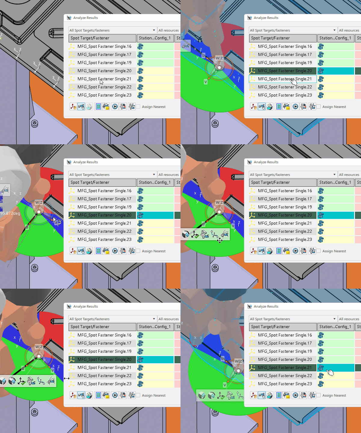
Modify the orientation of the gun around the approach axis using the
manipulator, as well as modify the position and orientation. Click
Commit Position
 in the
context toolbar to save the modified location.
The new position is saved, and the color of the cell for the selected target becomes green.
- Close the Analyze Results dialog box when finished.