Implementation of V6 Continuous Motion | ||
| ||
Primary Motion Planning Technique
- Find the joint angles at the both the start and the end targets using (regular) inverse kinematics. Note that the end target may have a different (wrist) config. Also, once the end target's joint values are determined, then the turn number values are applied. Then find the change from start to end position for the wrist joints. Note that a separate motion planning object needs to be created to manage the interpolation of the wrist joints.
- Find the distance along the trajectory (along a line or possibly along a circle).
- Compute the amount of time to move the TCP along the trajectory and the times for the wrist joints to complete their motions (which yields a total of four time values: one for the TCP and three, one for each wrist joint). The largest time value is the motion time which is determining time. All of the other components need to be slowed down to this time. The result is that the TCP and the wrist joints all take the same amount time to complete their motion.
-
During simulation, at each time step:
- Find the position along the trajectory (as a DNBXform3D).
- Find the wrist joint values.
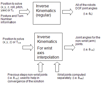
- Call special version of inverse kinematics (i.e. arm inverse kinematics), with the position along the trajectory (the result from part a). The wrist joint values (from part b) also need to be supplied as well. Since the wrist joints are being computed separately, you need to be aware of the inverse kinematics so that the position of the non-wrist joints will keep the TCP position along the planned trajectory. In its computation, the special version of inverse kinematics uses iterations to obtain the solution. To reduce the number of iterations, the values from the previous step are supplied so that the solution can converge at a quicker rate (with less chance for error). The following image explains the difference between the regular and the special version of inverse kinematics.
-
For the final result, the values from the call
to IK (from step 4) are merged with the interpolated wrist joint
values (results from step 3).
Note: The term continuous motion is often referred to as flyby and/or corner rounding.Without continuous motion (default setting), trapezoidal velocity profiles are typically used to determine the motion or a robot. If a velocity profile is graphed against time, the resulting curve resembles a trapezoid, since the velocity changes over the trajectory motion due to acceleration at the beginning and deceleration at the end. See image below for an example of such a profile. To keep the model simpler, all three phases are linear in nature. That is, they are in the form:
- Output = A * Input + B
- V2 = V1 + A * t
- D = V1t + 0.5 * A * t2
- (V2)2 = (V1)2 + 2 * A * D
- D = 0.5 * (V1 + V2) * t
- V1 and V2 correspond to initial and final velocities
- A equals the acceleration (or deceleration)
- D equals the displacement
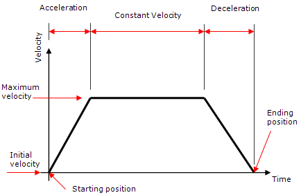
When a motion is performed, users specify the target position (the current position is the starting position), maximum speeds or motion time and type of motion/interpolation (i.e. linear/circular/joint). The acceleration and deceleration values are specified by the device. Once all of the motion attribute values are specified, the motion time for each DOF joint (for joint based motion) or for the TCP position and orientation (for Cartesian based motion) is determined.Note: Multiple independent items are participating in the motion (i.e. multiple DOFs or TCP position and orientation) and each may have different travel distances, speeds and accelerations can take a different amount of time.Once all of the times are determined, the largest time (referred to at the reference time) among the set of DOFs or TCP position and orientation is found. All motion elements/items are then scaled to this reference time; that is all non-reference items are all slowed down so that they all take the same amount of time to move. The times in each region are lengthened by an appropriate amount so that the total will be the longest time.
Rationale for Continuous Motion
Using trapezoidal motion profiles, the default behavior for the robot is to decelerate and stop at each target, and then accelerate to the next target. Consequentially:
- The velocity when moving through a set of targets is not constant.
- Stopping at each target increases the cycle time.
The image below shows the stopping
at each target. These two points are the main reasoning for continuous
motion.

Constant velocity motion is necessary for certain applications such as applying glue to the edge of a part; that is a constant velocity is necessary so that a constant amount of glue can be applied. Certain targets need to be stopped at so that an operation can be performed (such as a weld), while other targets do not need to be stopped at. By not stopping at these targets, the cycle time can be shortened.
Key Points for Continuous Motion
There are multiple techniques to implement continuous motion (for example various formulaic/mathematical techniques). The one chosen for this technique is to simply allow neighboring (or consecutive) trapezoidal motion profiles to overlap (by a small amount). Also it is important to note that profile that is considered is the reference profile; that is the profile of the element that takes the longest amount of time to move. The key points about motion profile overlapping are:
-
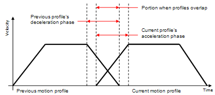
The overlapping of the profiles only occurs during
the deceleration phase from the previous profile and the
acceleration phase for the current profiles, see picture below.
-
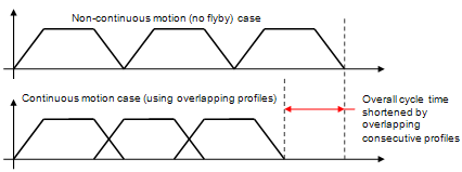
By overlapping the profiles the overall cycle time
will be shorter. This can be seen in the image below.
- The motion when the profiles do not overlap is the same as with non-continuous motion case; that is the computed positions will not deviate from the main non-continuous motion (zero flyby) trajectory.
- When the profiles overlap the motion will be a vector sum of the positions from both profiles. If there is a change in direction at a particular target, the resulting trajectory from this sum will deviate from the planned trajectory for the target. This deviation is the characteristic corner rounding (flyby) motion. Also, the amount of deviation varies with when the next profile is considered.
- This is technique is dependent on the motion time of consecutive motion profiles. Hence, there should be no special cases or versions to handle different motion types or other particular items (such as time based motion or short positional changes with large orientation changes). This also results in simpler code with less chance for errors to be introduced.
Circular Motion with a Via Point
The circular trajectory is specified as using three
points: start, via and end. Using simple geometry it can be easily shown that there is one unique
circle that passes through three points. Note that all three of
these points need to be distinct (otherwise we would have infinite
solutions). Therefore start, via and end points need to be all distinct
positions (orientation is not part of this check) otherwise an error
will be reported. Also, if all three points are collinear, then the only possible circle
that can go through these points would have an infinitely long radius;
this case is check and not possible. The trajectory that is specified from the three points only defines a
circular arc (part of a circle). To move in a complete circle another
circular move needs to be done to perform the remaining portion of the
circle. The following image shows the resulting circular motion, and how
different directions about the same circle are chosen by the via point
that is used.
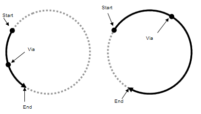
In Teach, you can then specify this in two steps. One entry for the via
point, and another for the end point. The start point is the robot's
initial position or the position of where it finished the previous
motion at. This can be seen in the next image, where one target is
denoted the via point by giving it the "Circular Via" motion type, and
the end point completes the circular motion using the Circular Move
motion type. The start point of the circular motion is where the
previous (Joint Move) finishes its motion.
| Cartesian | Join Move | Default | |
| Joint | Circular Via | Default | |
| Joint | Circular Move | 1_Axis | Default |
Also, circular motion is performed in the Cartesian coordinate space. Targets can be either joint or Cartesian, however when the calculations are done all points are converted into Cartesian coordinates. Finally the orientation is interpolated similarly to linear motion (1, 2, 3 and wrist axis) from the start to the end target. The orientation of the via point is not used for the orientation interpolation. The via point is used to compute a unique circle and then to determine which direction along the circle motion occurs.
Circular Motion Depending on Previous Motion
If the previous move is a circular or linear, then the via point does not need to specified. Instead it is computed. Rather than computing a circle that goes through three points, it is computed using a target point and a tangent.
If the previous move is linear, then this (non-flyby) trajectory is used as the tangent. For a previous circular move, the tangent is computed at the end point of the circle.
Once a circle is found that is tangent to the previous move and goes through the target, a point (i.e. via point) is found on this circle which is on the shorter portion between the tangent point and target point. Then the same code is called using the tangent start (as the start target), the computed via point, and the specified target (as the end point).
In Teach, you have something along the lines in the image below.
| Cartesian | Joint Move | Default | |
| Joint | Linear Move | 1_Axis | Default |
| Cartesian | Circular Move | 1_Axis | Default |
Wrist Axis Interpolation
The DELMIA default motion planner supports two types of Cartesian-based motion:
- Linear
- Circular
There are two variables to consider when performing the move, namely the position and orientation. The position is determined by the geometry of the trajectory (i.e. straight line, circular arc). However, there are many different techniques to interpolate the orientation, for example rotating a single angle value about a single representative axis. Note that the position and orientation are interpolated so that they both move simultaneously.
For most robots a certain set of joints determines the position and another determines the orientation. Usually the position is found using joints 1, 2, 3 (also called the arm joints), and the orientation is found using joints 4, 5, 6 (or the wrist joints). For Wrist Axis interpolation, instead of the absolute orientation of the motion target being interpolated, the wrist joints are interpolated separately using joint interpolation. The arm joints are then determined using a special version of inverse kinematics that also uses the interpolated wrist joints an input (along with the tcp position along the trajectory). Since, the wrist joints are interpolated separately there are three important differences compared to other interpolation modes:
- It is possible to set Turn Numbers for the target and apply these to the wrist joints during motion.
- The special version of inverse kinematics is able to handle going through a singularity during the motion.
- Tt is possible to set the target with a different wrist configuration compared to the start (i.e. do not flip wrist to flip wrist) and apply these during motion.
Due to the special inverse kinematics adjustment, the robot's IK solver needs to be enhanced to support Wrist Axis interpolation. This enhancement has been provided for all robots with generic inverse kinematics of articulated class, and also for robots with the following device-specific inverse kinematics:
- kin_abb_irb2000
- kin_abb_irb6400c
- kin_abb_irb90
- kin_abb_irbl6_6
- kin_motoman_k10s
- kin_shinmaywa_rjh140
- kin_s10
- kin_s10up
- kin_s400
Assigning wrist axis interpolation to a robot with any other type of inverse kinematics results in the default 1 axis interpolation.
Note:
The special inverse kinematics adjustment required for Wrist Axis interpolation may result in certain TCP positions/orientations being unreachable that would otherwise be reachable with standard inverse kinematics.
This type of unreachability typically manifests during the linear or circular interpolation in the middle of the move (the start and end of the move will continue to be reachable, but the motion between these points may cause a halt). This issue can be identified by changing the orientation interpolation type (to 1 Axis, for example) and verifying that the motion completes. If this is the case, try modifying the target positions in the robot task and retry the Wrist Axis interpolated motion so that it can go through from start to end.