Creating Tool Frames

This procedure explains how to create a tool frame.

A robot tool frame can be defined either as the standard tool frame or a stationary tool frame.

This task shows you how to:


Before you begin: To perform this procedure, you must have a robot and at least one robot task defined.

Define a Standard Tool Frame

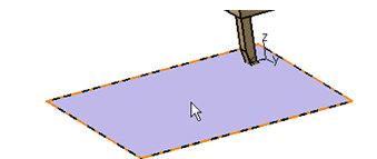
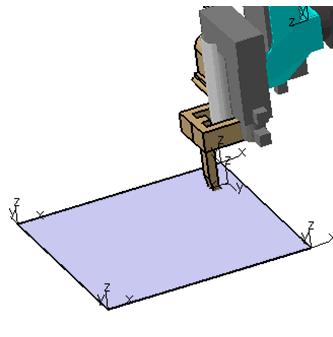
This task shows you how to define a standard tool frame. The standard tool frame is at a user-defined offset from the robot's flange and it moves with the robot. You define the offset between the flange and the tool frame. You can define the actual reference location from which the offset is applied.

  1. In the Motion Controller section of the action bar, click Tool Profile .
  2. Select the robot from the tree. The Tool Profile dialog box appears.
  3. Click Set TCP.
    The Set TCP Offset dialog box appears. It shows one of the following:
    • The offset is inherited from the tool frame definition of the device (e.g., a spot weld gun).
    • You can define the offset.
  4. Is the offset defined through inheritance from the tool frame?
    • If YES, no settings are required.
    • If NO, then define the offset between the flange and the tool frame. You define the actual reference location from with the offset is applied.
  5. Click OK in both the Set TCP Offset and Tool Profile dialog boxes.

Define a Stationary Tool Frame

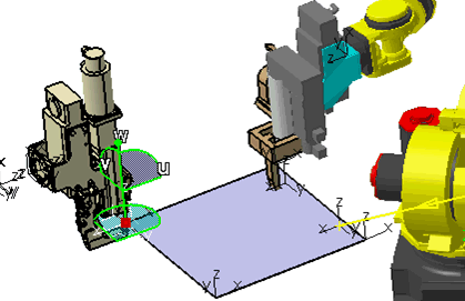
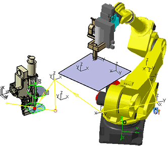
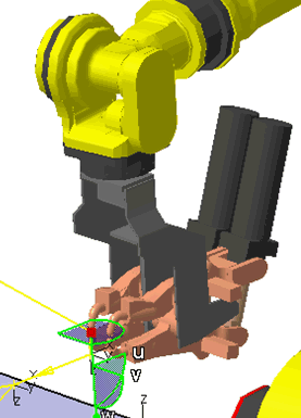
This task shows you how to define a stationary tool frame. The stationary tool frame represents an alternative way of defining a tool frame. In case of a stationary tool frame, the roles of the robot and the tool are reversed. Instead of the robot carrying the tool to the workpiece, the robot carries the workpiece to the tool for processing. This kind of application is being used in cases when the tool is too large or too heavy to be carried by the robot while the stationary tool frame is fixed in space and motion of the robot does not influence tool's position or orientation.
  1. In the Motion Controller section of the action bar, click Tool Profile .
  2. Select the robot from the context menu.
    The Tool Profile dialog box appears.
  3. Select Stationary.
  4. Click Set TCP . You can set the location of the frame by doing one of the following:
    • Set the TCP by manipulating the orientation Robot location directly.
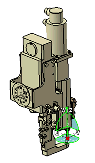
    • Set the TCP values in the Set TCP Offset dialog box.
    The stationary tool frame is created.
Use a Stationary Tool Frame in Teaching Tasks

This task shows you how to use a stationary tool frame. You designate a tool frame as stationary so that the robot is carrying the workpiece instead of the tool. The typical roles of the tool and of the workpiece are reversed. Instead of the robot moving towards the target point, the robot in effect brings a target point to the stationary tool frame. As a result, incorporating a stationary tool frame into robot task requires some modifications of the tag group and tag creation task.

  1. Click New Tag Group .
  2. Select the owner.

    In this example, Part1 needs to be selected as an owner of the tag group.

  3. Click New Tag to create the tags for the newly created tag group.

    Note: Tags only represent locations on the workpiece. Tags contain no motion information of any kind. Motion information is provided through Teach and creation of motion operations.
  4. To create operations, that is, to program a task, click Teach a Device .
    The Teach dialog box appears.
  5. Select the Jog check box.
  6. In the Cartesian tab, set the currently active tool frame to the stationary tool frame.
  7. Select the tag point.


    The robot moves in order to provide the tag point to match the stationary tool frame.