Creating a Grid of Tags | ||
| ||
-
Click New Grid-based Tags

The Grid-based Tags dialog box appears.
Note:In Live Simulation, you can right-click an existing tag thumbnail in the immersive browser and select New Grid-based Tags:
In this case, you can skip directly to Step 5 after selecting New Grid-based Tags.
-
Click New TagGroup
 .
.
The Grid-based Tags dialog box becomes hidden and you are prompted to select a product to create a tag group under.
Note: You can also select an existing tag group. -
Select
 to create the new tag group.
The Define Plane dialog box appears.
-
Select the location where the grid will be placed.
-
Click OK in the Define Plane dialog box.
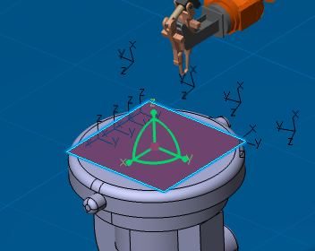
A grid appears at the selected location.

-
Use the Grid-based Tags dialog box to define the grid.
The Length, Width and Height of the grid can be modified with the controls provided in the Grid-based Tags dialog box.
- The number of cells in the X and Y directions is defined by X# and Y#, respectively.
- The number of grid layers is defined by Z#.
- You can deselect Height to make the grid 2 dimensional (it becomes a single layer).
Tags can be created at the center of each cell or at the corners.
Select Preview to see the tags that will be created based on the current dialog box settings.

- You can also directly manipulate the dimensions of the grid in the work area by dragging its borders.
- You can change the position and orientation of the grid in the work area by dragging and dropping the orientation Robot onto it.
- When viewing a multiple layer grid, you can double-click any 2D layer to hide the other 2D layers and switch to a top-view. (Note that you can no longer drag the borders of the grid in this mode.) Double-clicking the 2D layer again switches back to the previous view.
-
Click to create the tags as defined by the grid.
The tags appear in the work area, and the grid is no longer displayed:

The new tag group appears in the tree.