Configuring the Server to Store Position Matrix Information

This task provides useful information regarding the configuration of a server to store position matrix information for CATIA assemblies or models, PRO/Engineer®, NX® assemblies or models, and for Engineering BOM Management Part assemblies.

This task shows you how to:

CATIA Assemblies or Models

The server needs to be configured to store the positional information of components of an assembly. Only then can these assemblies be viewed in the In-place mode in the X-CAD Design Management connector. Currently, the positional information is captured and stored when an assembly (i.e. CATProduct) is checked into the database from CATIA using CT5 integration.

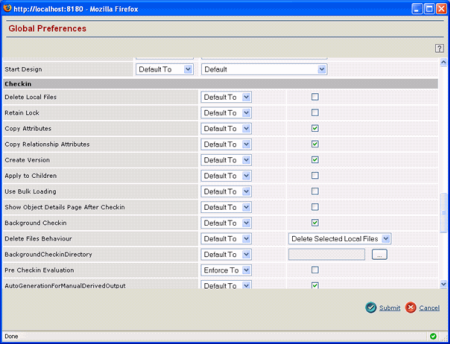
To store the positional information of components in an assembly, an administrator should configure the Collaborative MultiCAD Management server CATIA GCO (Global Configuration Object) as described below:

  1. Start the application server.
  2. Log in as an administrator user (you should have Business Administration privileges).
  3. Select Actions > Designer > Global Preferences from the menu. The GCO Chooser dialog box appears.
  4. Select the CatiaV5NewArch option and click Submit.


    The Global Preferences dialog box appears.

  5. In the Global Preferences dialog box, scroll down to the Checkin heading and select the Copy Relationship Attributes preference.


  6. Click the Submit button to save the changes. With this configuration, when a CATProduct i.e. an assembly is checked in from CATIA, a Part structure with position matrix information is created in the database.

    Note: The positional matrix is a string attribute called Spatial Location on the CAD subcomponent relationship between the parent and the child Part. Below is a view of the CAD subcomponent relationship using the thick client.


PRO/Engineer®, NX® Assemblies or Models

A similar server configuration is required to store position matrix information for PRO/Engineer® and NX® models. This can be done by modifying the respective GCO object related to PRO/Engineer® or NX® as done for the CATIA GCO.

See step 3 above to select the GCO that corresponds to PRO/Engineer® or NX®.

For Engineering BOM Management Part Assemblies

The following server configuration is required to copy position matrix information from CAD models or assemblies to Engineering BOM Management Part assemblies. Typically, you perform an EBOMSync operation to copy content from CAD assemblies to Part assemblies.

  1. Open the Run MQL window:
    1. From the compass, select Social and Collaborative Apps .
    2. In the list of apps, click Collaboration and Approvals.
    3. In the navigation pane, click Utilities > Run MQL.
    To run an MQL command, enter the command in the MQL Command box and click Run or press Enter.
  2. Run the following commands:

    set context user admin
    mod bus “MCAD-EBOMSyncConfig” “MCAD-EBOMSyncConfig” “–“ attribute IEF-EBOMSync-RelAttrMapping “CAD SubComponent|Spatial Location|EBOM|Component Location”

  3. Optional: If users have already accessed the app, you will need to delete the corresponding LCO. This forces the system to create a new one using the latest GCO as a base.

    del bus MCADInteg-LocalConfig “USER_LOGIN_NAME” 1

    where:

    USER_LOGIN_NAME is the user who logged in before step 1 was done.

    For more information, see X-CAD Design Management Installation and Administration: Configuring and Setting Preferences.