- From the Wireframe section of the action bar,
click XYZ Automatic Planar Sections
 . . -
Select the Element to cut (Clouds of points, meshes, surfaces, or volumes).
A context menu is available on the selection.
-
Optional: Edit the Sag value used to tessellate
volumes or surfaces.
Whenever you modify the Sag value, the tessellation is
restarted.
- When working with clouds of points, define the Influence area (computation area around the cutting planes).
When the points are not dense, a cutting plane (black
line below) may be unable to intersect the points. The Influence area is the area shown in
yellow that contains the points considered to intersect the cutting
plane.

-
Select the axes of the current axis system to take into account.
By default, all three axes are selected.
- Define the Start and Stop values to create the planar sections only on a portion of the selected elements.
- Select Auto-range: Start and Stop values are adjusted automatically for each direction, depending on the elements selected.
- Or clear Auto-range and input your own Start and Stop values.
-
Define the Offset from the axis system origin along each axis.
- Define the Step between planar sections.
-
For each axis, select the Color of the planar sections.
- Click Apply to display changes on cloud of points.
Changes are dynamically displayed on tessellations.
The cutting planes in each direction are displayed in the work area. They are created as explained in About Planar Sections. 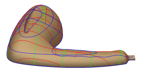
|