Working with Drafting | |||
| |||
-
Our example is based on those meshes:
- Open your model.
- Go to Drafting.
- In Drafting, click Front View
 .
. - In the tab where the meshes are, select a plane.
On the sheet, a blue knob appears, as well as a green frame containing a preview of the view to be created.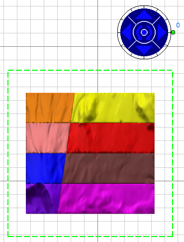
Note: Use the handles of the knob to define the location and orientation of the view to create. -
Click the drawing sheet or at the center of the blue knob to generate the view:
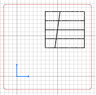
-
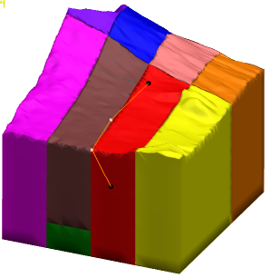
Generate a section cut of the meshes:
- In Drafting, click Aligned Section Cut
 .
. - In the tab where the meshes are, select a sketch that defines the section.
The sketch is added to the drawing and a preview of the Aligned Section Cut is displayed: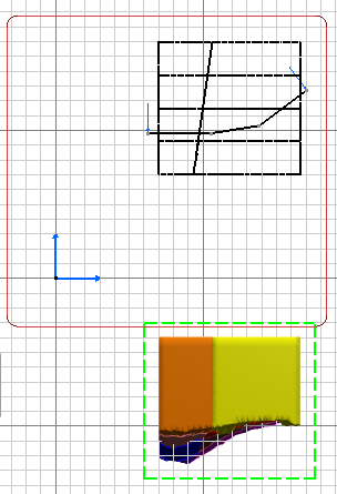
- In Drafting, click Aligned Section Cut
-
Generate a section view of the meshes:
- Proceed as in step 3., but click Aligned Section View
 .
.
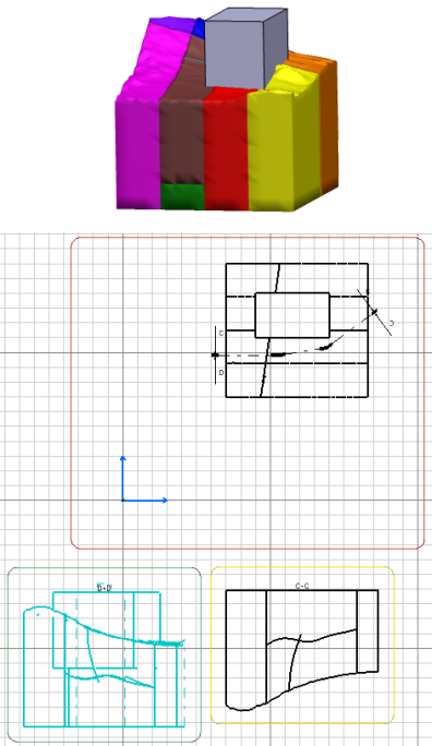
All these views are on one sheet:
- Proceed as in step 3., but click Aligned Section View
Notes:
- Graduations are not generated automatically, even in section cuts.
- Elements other than meshes can be taken into account: