Experiencing Motion Study of Mechanisms | ||||||
|
| |||||
-
Sketch each body of the mechanism with a closed profile.
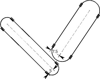
-
Group these profiles to represent a body of the mechanism using
Group
 .
.
The origin and the absolute axis of the sketch are treated as immovable.

-
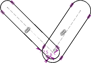
Create the relations of the mechanical system:
-
Apply coincidence constraints between the two profiles that
are grouped together, as required.
Internal constraints of each body are irrelevant to the kinematic system. Only external constraints are considered for the kinematic relations between bodies of mechanism.
-
Anchor or ground the bodies to make them immovable using
Fix
 .
.
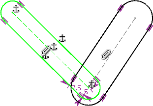
- Use other Sketcher capabilities to create a feasible mechanism.
The nature of the relation between the bodies is a result of the degree of freedom between the two bodies. The constraints you apply on the mechanical system decide the kind of motion between them. For example, the fixing of a body leads to its immobility whereas the coincidence and angle constraints lead to a revolute joint.
-
Apply coincidence constraints between the two profiles that
are grouped together, as required.
-
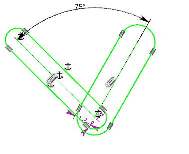
From the
Compass,
click
Play
 .
.
- You are now in the motion study environment. the bodies are filled to clearly define the presence or absence of material. This helps in defining a body inside a body.
- The detected relations between the two bodies appears with
 icon for a rotation based relation and
 for a translation based relation.
- The Play section is added to the action bar.
-
Click
 to create a trace of this body at the particular position.
This is useful to visualize clearances, check feasibility, or redesign the shape of the body by editing its associated grouped body in the sketch.

-
Click
, followed by
 on the
context toolbar
to create an angular motor in the mechanism.
on the
context toolbar
to create an angular motor in the mechanism.
If a linear link is recognized for a joint, click
, followed by
 on the
context toolbar
to create a linear motor in the mechanism.
on the
context toolbar
to create a linear motor in the mechanism.
- Optional:
To define a contact between two bodies:
- Press Ctrl and select the bodies.
-
On the context toolbar, click Contact
 .
.
A contact between two parts simulates the move of one part by another part. The contact is responsible for displacement or stopping of a part due to the other part.
Note: To delete the contact, select the bodies in contact and on the context toolbar, click Delete Contact .
At the time of simulation, the contact between these bodies is considered during the dragging of bodies and during the modification of angle and distance parameters.Note: For two bodies in contact, one filled body cannot cross or pass over another filled body.
.
At the time of simulation, the contact between these bodies is considered during the dragging of bodies and during the modification of angle and distance parameters.Note: For two bodies in contact, one filled body cannot cross or pass over another filled body. -
In the action bar, click Play Forward
 .
The mechanism can be now experienced.
.
The mechanism can be now experienced.The Play section includes the following commands:
Command Description 
- Step Backward
- Goes back to the beginning of the scenario.
- Play Forward
- Plays the scenario.

- Step Forward
- Moves to the end of the scenario.

- Decrease Speed
- Decreases the scenario speed.

- Pause
- Pauses the scenario.

- Increase Speed
- Increases the scenario speed.
-
From the action bar, click
 or from the Compass, click Play
to exit the motion study environment.
or from the Compass, click Play
to exit the motion study environment.
If you re-enter the motion study environment in the same session, the values you assigned are restored.
Notes:- Since the values assigned to the motor are based on the constraints you apply to the sketch, the motor is reset if the concerned constraints are removed.
- To not retain the values assigned to the motor, delete the motor and assign new values.
-
To create and generate a trace, perform the following steps:
- Create a sketch containing a group of geometries.
- Add one or more points to this group.
- From the Compass, click Play
. Note: You are now in the motion study environment.
- Click the sketch and then click Create Trace Point
 in the context toolbar.
 - Drag the selected part or move it using the Robot.
A red
 trace appears. It disappears when you click Stop and
Rewind
trace appears. It disappears when you click Stop and
Rewind
 or switch back to the design environment.
 Notes:
- The construction points of a group are not considered for creating trace points.
- The accuracy of a trace depends on the number of simulation steps.
- To generate a permanent trace, select the red trace, and then click Generate
Trace Point
 in the context toolbar.
 - From the Compass, click Play
.
You are now in the design environment. A dotted polyline line is created corresponding to the trace.

Notes:- You can add two or more points to the group to create two or more traces simultaneously.
- You can also create a trace using an Angular Motor or a Linear Motor attached to the part.