Scaling Elements | |||
| |||
-
From the Sketch section of the action bar,
click
Scale
 .
.
You can first select either the geometry or the command. If you select the command first, you cannot multi-select elements.
By default, the Duplicate check box is selected which means that the 2D elements you select are copied.Note: Apart from the Duplicate check box, the Keep internal constraints, Keep external constraints, and Keep original constraints mode check boxes are cleared, by default.However, after you execute this command, your preferences are stored and saved for the next usage.
-
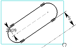
Select the elements to be scaled.
-
Click to indicate the center point on the geometry.
You can define the center point from its coordinates in the Tools Palette boxes.

-
Click
OK to confirm.
A context toolbar appears showing available constraints. The geometry is scaled.

-
Click anywhere in the
work area.
Internal constraints and external constraints are preserved but revalued.

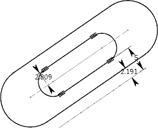
Notes:- If you clear the
Mode check box, the geometry is scaled
without preserving the original constraints mode (driving/driven) as shown
below.

The constraints defined in the original geometry are driving constraints. These constraints are not copied in the resultant geometry (because the Mode check box is cleared) which shows reference constraints.
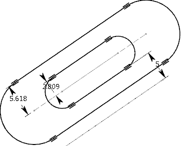
- If you clear the
Internal check box keeping
Mode selected, the internal constraints
are not copied in the resultant geometry as shown below:
- If you clear the
External check box keeping
Mode selected, the external constraints
are not copied in the resultant geometry as shown below:
- If you clear the
Mode check box, the geometry is scaled
without preserving the original constraints mode (driving/driven) as shown
below.