You can offset an entire profile and
manage the offset between the base profile and the offset profile.
The
Profile Offset constraint maintains all the
elements of the profile in parallel.
Before you begin: Ensure the following:
The profile to offset has only one domain with simple geometries
like arcs, circles, and that there are no self-intersecting elements in the
profile.
Select the
Dimensional Constraints and the
Geometric constraints from the
Sketch section of the
action bar.
Select the created profile.
From the Sketch section of the action bar,
click
Offset.
Tip:
In the
Tools Palette, select
Both side offset to create offset on both sides.
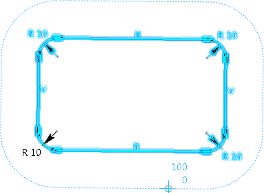
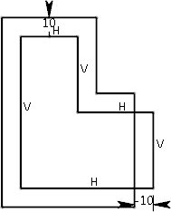
Offset profile is previewed in dotted lines
In the
Tools Palette, specify the required offset.
You can also move the cursor in the work area to achieve the required offset.
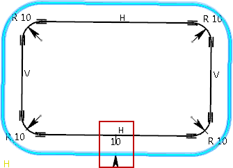
The offset of the profile is created
and the distance between the base profile and the offset profile is displayed.
This ensures the parallelism of the two profiles.
The profile offset constraint is displayed
You can create an offset to the profile only if the following
conditions are met:
The topology of both profiles is identical.
Both profiles have same number, type, and arrangement of
geometries.
Both profiles contain simple geometries like arcs, circles, and
lines that are not self intersecting and are mono-domain.
Select the profile and move one of the geometries in the profile.
A parallelism at a given distance is maintained between the
two profiles during the move.
Double-click the offset value in the
3D area
to open the
Parameter Definition dialog box or double-click
the
Profile Offset node in the
tree
to open the
Profile Offset Definition dialog box and change
the offset value.
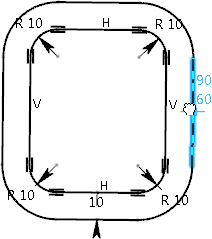
The global offset value is changed. The
offset value between all the elements is changed uniformly.
Change in global offset value
To change the local offset values:
Double-click the
Profile Offset node in the
tree
to open the
Profile Offset Definition dialog box.
Under
Local values, change the local offset
values for different elements individually.
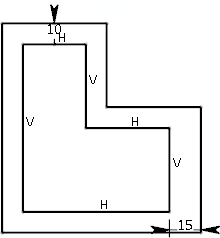
The local offset value is changed
without disturbing other geometrical elements.
Change in local offset value
You can also have positive and negative local offset.
Positive offset
Negative offset
Break, trim, chamfer, corner, or remove elements in the base or
offset profile.
Only the modified element is modified or removed. The rest
of the profile remains consistent. The profile offset constraint is active. If
you remove all the elements of either base or offset profile, the profile
offset constraint is broken and is removed.
Optional:
Select all the geometries of both profiles and perform copy paste
operation.
The profile offset constraint is copied and pasted.
 and the
 from the
 .
.
 to create offset on both sides.