Hardware Diagram Structure
A hardware diagram is created in a view and is linked to the topology tree or the rack tree.
To create a diagram, click Create View from the tree.
A topology or a rack can be attached to several diagrams.
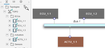
Hardware Diagram StructureA hardware diagram is created in a view and is linked to the topology tree or the rack tree. To create a diagram, click Create View from the tree. A topology or a rack can be attached to several diagrams. Elements of a Hardware DiagramIn a hardware diagram, you can insert different elements. EE ComponentsEE components are represented by a box. For a rack, the position of EE components is also
displayed. Each EE component has its own color:
EE Component PortsEE component ports have the following representations, which depend on their type:
Note:
With the Avionics Architect (AVARA) role, you can create an AFDX/ARINC 644 connector.
Hardware PortsHardware ports have the following representations, which depend on their type:
EE ChannelsEE channels are represented by a box or by a line:
Note:
With the Electrical, Electronics and Software Architect (ELAET) or Electrical and Control Architect (EEWCI)
roles, you
can create VLANs.
ConnectionConnections have the following representation:
|