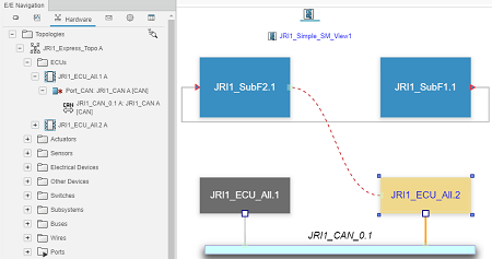
In the system mapping diagram, you can show elements from the
associated topology and either from the associated function or the software
component.
Ports
EE component ports, functions/subfunctions ports, and software ports
have the following representations depending on their type:
| Port
|
Representation
|
Color Code
|
| Functional port
|
In:

Out:
|
 Mapped port. Mapped port.
 Unmapped port. Unmapped port.
 Unmapped port with some, but not all, of its
subflows mapped. Unmapped port with some, but not all, of its
subflows mapped.
 Local port. This port does not need to be mapped. Local port. This port does not need to be mapped.
 Unknown status. Waiting for the mapping of the
functional. Unknown status. Waiting for the mapping of the
functional.
 Partially mapped port. The bus is referenced but
the signal is not yet identified. Partially mapped port. The bus is referenced but
the signal is not yet identified.
|
| Software: Sender-receiver port |
Read:

Write:

|
Mapped port.
Unmapped port.
Unmapped port with some, but not all, of its
subflows mapped.
Local port. This port does not need to be mapped.
Unknown status. Waiting for the mapping of the
functional.
Partially mapped port. The bus is referenced but
the signal is not yet identified.
|
| Software: Client-server port |
Read:

Write:

|
|
| Hardware
|
Wired In:

Wired Out:
Wired InOut: 
Other ports:
|
|
Connections
Connections have the following representation:
| Connections
|
Representation
|
| Connection between ports
|

|
|
Computed path of connections for functions and software
components:
When a data passes through a few levels of an object
hierarchy, the whole pathway is displayed by a green dotted line.
This line is displayed between allocated objects or most inner objects, when no allocated
objects are involved in the path.
|

|
 from the tree.