- Create logical and physical data as described below:
- An electrical logical system containing equipments, harnesses, single insert connectors, harness
bundles, electrical physical systems and
branches. For more information, see Functional & Logical Design User's Guide: About Electrical Logical
Systems.
-
A physical structure containing equipments and electrical
physical system.
- Only the logical and physical roots are linked through implement relation.
- Both logical equipments have pre-defined part number. Three instances are created in physical.
-
Open the logical and physical data:
-
From the
Search Results panel, right-click the logical or
the physical root and select
.
For more information, see System Finder User's Guide: Exploring RFLP Structures.
Both logical and physical roots are explored in System
Finder.
-
In the tree, select both roots and select
Open in the context menu.
-
Activate the physical root product in Generative Electrical 3D
Design.
-
From the
Generative Electrical 3D Design section of the action
bar, click
Logical to Physical
 . .
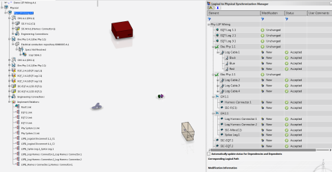
The Logical to Physical Synchronization Manager
dialog box appears. The name of the selected element is displayed in the dialog box. -
Select the physical root product in the dialog box and check the
Scan and resolve links option.
- Click Scan Links.
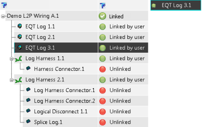
Data is analyzed to find existing implement links between the logical and physical. The result is displayed with the logical tree structure and their link status.The result is filtered for Unlinked status, so only elements with Unlinked status and elements required to maintain the tree structure are visible. - Select a logical wire harness or an equipment. You can see the compatible physical elements in the corresponding tab.
- Select a physical element proposed in the Logical to Physical dialog box.
The red bullet turns green in front of the logical and physical elements and the logical equipment comment changes into: Linked by user.  Notes:
- When you select a logical component, you can see the Corresponding Physical Path in the second frame of the dialog box.
- The scenario above shows you that you can select the compatible physical element in the dialog box. But if you click Select element, then you can also select it directly in the tree.
-
Once you have created the missing implement links, click Analyze.
The analysis is performed depending on the physical elements selected by the user. A report is displayed. Note:
If the update of implement links is not performed, the Logical to Physical synchronization behavior remains unchanged.
The Modification column informs you about the link analysis / update of the physical elements: In the Status column, you can accept, refuse or ask for validation via the context menu. If you select Accept, the component with its implement links will be synchronized. In the User Comments, you can also create your free text. The logical elements which have been connected to physical elements are seen as Unchanged because only implement links have been created, without instance modification. In this case, the context menu for user validation is not available: - Click
 to see the analysis report at the bottom of the dialog box. to see the analysis report at the bottom of the dialog box.This is the same information as that of the HTML Report  . Note:
If you select the Automatically update status for Dependencies and Dependents option, the warning is not displayed (cf. step 5 in Synchronizing Logical Data with Physical Data).
- Click
 to see all the modifications (accept / reject status) done by the system. to see all the modifications (accept / reject status) done by the system. - Click Synchronize.
The physical data is synchronized with the logical data. Implement links between logical and physical selected during Scan and resolve links stage are created.  - Click Close.
-
Create branches, and then route the conductors.
-
From the standard area of the action bar, click Link Review
 (or Network Assistant (or Network Assistant  ) to validate the network created by the logical to physical synchronization. ) to validate the network created by the logical to physical synchronization.
- Click Scan Links.
Only the Unlinked elements are displayed. All the elements for which implement links were created in earlier synchronization have the Linked status and are filtered.
|