Arranging Segments at Junction | |||||
|
| ||||
-
From the Branch section of the action bar, click Arrange Segments at
Junction
 .
.
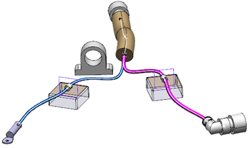
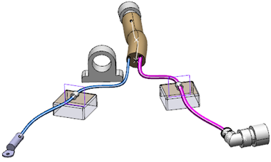
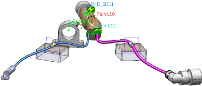
- Move the pointer over a segment meeting at junction to display a red dot and arrow at this junction.
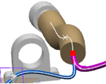
- Click the target segment.
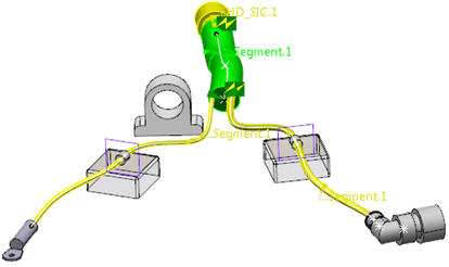
- Valid source / reference segment is automatically identified by the
command and it is colored green. This selection is based on the
following conditions:
- segment having a maximum diameter at junction point, among all the segments meeting at junction.
- If junction is at the support point (only one point of support), then the segment is connected to the segment selected by the user and it is routed through the support.
- If none of the segments is routed through the support, then the segment with maximum diameter will be considered as the reference segment.
- If junction is at the branch point, then the maximum diameter segment from the branch owning the branch point will be considered as the reference segment.
- A target segment and a source segment cannot share the same branch curve.
- You cannot merge branches, the one of which is a source for arranged segments at junction.
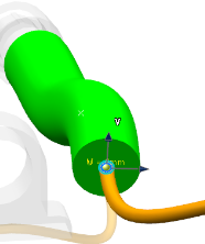
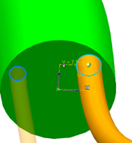
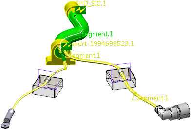
The Arrange Segments dialog box is displayed.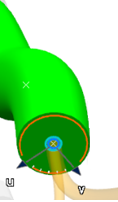 Notes: The Arrange Segments at Junction command automatically checks if it is a valid junction and if any target segments exist for arrangement. To distinguish the element in the work area, colors are applied on the 3D view of the objects.
- The reference segment (large bundle) is automatically identified and it is colored green.
- Valid segments for arrangement are displayed as transparent orange.
- Other elements (supports, devices,...) are in transparent white.
- Default U and V directions at junction are visible.
The Arrange Segments dialog box contains information about:
- Reference Branch / Segment (not editable): contains the string identifying the reference segment (or source segment) on whose surface the other connected segments will be arranged.
- Branch Segments meeting at the Junction (not editable): lists all the target segments meeting at the common junction and that will be arranged.
- Advanced parameters: are editable during segment arrangement via this dialog box editor or by dragging the green bullet in the work area (see the steps further down).
For more information about the Activate clipping plane option, see Arranging Segments in Supports Manually.
- Valid source / reference segment is automatically identified by the
command and it is colored green. This selection is based on the
following conditions:
-
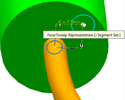
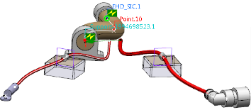
Click the orange handle to modify the U and V directions using the
degrees' handle.
The pointer changes, the handle becomes blue and the default U-V directions are displayed:

-
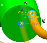
If you need to change the default U-V directions, then rotate the handle
with your pointer and you can use a measuring wheel.
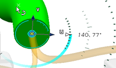
Tip: Click the degree's value and an editing box appears. You can enter a value and press Enter. -
Click in the work area to confirm the value and quit the
direction modification command.
Warning: Once the U-V directions are finalized, you can no longer modify them. Once the U-V directions are finalized for junction, you can arrange target segments one by one. The target segment is automatically selected in the Arrange Segments dialog box. You can select another segment in the list.
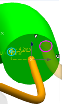
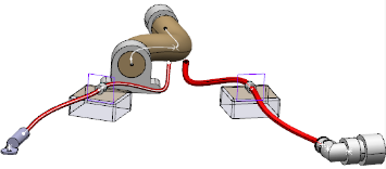
- Select the yellow sphere with your pointer and drag it on the source segment's surface to modify the target segment position.
Note: You can manipulate the target segment only on the current plane of the source segment's surface.While dragging the target segment, the corresponding U-V values are displayed (yellow).
- Click Apply.The position of the target segment changes.
-
Repeat the steps 7 and 8 for the other valid segment(s).
You can arrange the U-V directions of the selected target segment using the arrows of the spin box. -
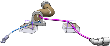
Click Apply to display the current arrangement.
- Click OK to finalize the arrangement of segments.
Note: If the same junction needs to be arranged again, select Arrange Segments at Junction and follow the same steps as explained above. -
From the standard area of the action bar, click Link
Review
 to show
the arranged segments' as distant electrical linked to the source
segment.
to show
the arranged segments' as distant electrical linked to the source
segment.
A distant link is created between the arranged segments and the source segment.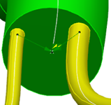 Notes:
- If a new segment is created and connected geometrically to an already arranged target segment (on another source segment), the new segment shares the end's representation of the arranged target segment.
- If this new segment is selected for arrangement, previous arrangement becomes erroneous. Such a case is not recommended because it may be difficult to identify the source segment.
You can modify the existing route of a reference segment, which is developed in the steps below.
-
Select the source segment and click Classic Branch
Definition
 from
the Branch section of the action bar in the Electrical 3D Part Design
app.
The Branch Definition dialog box appears.
from
the Branch section of the action bar in the Electrical 3D Part Design
app.
The Branch Definition dialog box appears. -
Select the Replace option.
-
Select the support.
-
Click OK in the Route
Definition dialog box.
The Route Definition dialog box disappears.
-
Click Update
 from the standard area of the action bar.
-
Select the root product and click Link Review
from the
standard area of the action bar.
-
Click the reference segment.
The segment arrangement is transferred onto the support with distant electrical links.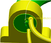
You can edit the target segments' arrangement within the support's route by clicking again Arrange segments at Junction (from step 7).