About Routing

Routing is the process of defining the path of a conductor. Routing allows you to define the electrical branch geometry layout that is required for a specific design.

This page discusses:

Routing Process

Once the system knows where the conductor ends are, routing can be done. You can also use a business rule to check the compatibility of the conductor to be routed and the set of segment to be routed through. When conductors are routed:

  • A network is built based on connectivity:
    • If any link is defined between electrical geometry and electrical physical system, then the network is searched in only the connected electrical branch geometry.
    • If no link is defined between electrical geometry and electrical physical system, then the network is searched in all the electrical branch geometries.
  • Entry points in the network are retrieved based on the segment connection points or cavity.
  • The algorithm is launched to find the route for all the conductors.

A conductor group is ready for routing if all its constituent conductors and conductor groups are ready for routing. This means in particular that all ends of the constituent conductors are correctly mapped.

You can create your own compatibility table to apply separation conditions when routing. This table is taken into account from the Separation Code File option specified in Me > Preferences > App Preferences > 3D Modeling > Electrical and Electronic Systems > Electrical 3D Design > Conductor section.

You can use the Validate Conductor Routing (EWRRouting_ValidateWireRoute) opening ID to check the compatibility of the conductor to be routed and the set of segment to be routed through. Thus, a message appears from the rule's context.

Calculation of Filling Ratio

The filling ratio of a segment is calculated based on the section area of its constituent conductors and conductor groups and on the section area of the segment.

Important: The calculation of the filling ratio is only possible when the Diameter and bend radius to its content option is cleared in Me > Preferences > App Preferences > 3D Modeling > Electrical and Electronic Systems > Electrical 3D Design > Conductor.

For more information, see Impact on Segment.

The formula used to compute the filling ratio of a segment is the following:

Note: The formula is the same for conductors and conductors groups.

The section area of conductors and conductors groups is calculated as follows:

For one conductor or conductors group

where:

  • is the section area.
  • is the radius of the conductor or conductors group.

For two conductors or conductors groups and above

where:

  • is the section area.
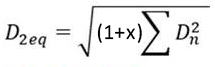
  • is the equivalent radius of the conductors or conductors group.
Note: The equivalent radius of conductors is calculated as follows:

Equivalent diameter of conductors / 2

For more information about the calculation of the equivalent diameter, see Formula below.

Calculation of Segment Diameter

By default, when the conductors are routed, the diameter of segments is calculated based on the diameter of constituent conductors and conductor groups.

Important: Calculation of segments diameter is based on the conductors and conductor groups when the Diameter and bend radius to its content option is selected.

To change this behavior, clear the option in Me > Preferences > App Preferences > 3D Modeling > Electrical and Electronic Systems > Electrical 3D Design > Conductor.

For more information, see Impact on Segment.

Note: Conductors with Specifications Fully Resolved or Not Resolved are used for the computation of the diameter of a segment. Conductors with Specification Resolved not Loaded are ignored for the computation of the diameter of a segment.

Diameter of Segments Containing Conductor Groups

The diameter of segments containing conductor groups is computed in two different ways depending on whether the conductor group is routed between two connectors, or between three or more connectors.

Note: The same rules apply when updating the bend radius.

Conductor Group Between Two Connectors

The segment diameter is based on the conductor group.

The formula used depends on the number of conductor groups in the segment. In the example below, the segment contains one conductor group. The diameter of the segment is the same as that of the conductor group.

Note: Changing the diameter of individual conductors does not affect the diameter of the conductor group and segment.

Conductor Group Between Three or More Connectors

  • If all the conductors in the group are routed together through the segment (S1 in the illustration below), the segment diameter is based on the conductor group.
  • If the conductors in a conductor group are routed separately through segments (S2 and 3 in the illustration below), the segment diameter is based on individual conductors.

The formula used depends on the number of conductor groups and conductors in the segment.

Diameter of Segments Containing Individual Conductors

Segment diameter is computed based on the conductors it contains, and segment geometry is updated.


Formula

The formula used to update the diameter of a segment depends on the number of conductors and conductor groups in the segment.

Number of Conductors and Conductor Groups Segment Diameter
0 No change
1 Equals the conductor's (or conductor group) diameter.
2 Equals the sum of the conductors' diameter.
3 and above Equals:

Where 0 <= x <= 1 is the percentage added to the equivalent area driven by the option Percentage added to equivalent area. For more information, see Impact on Segment.

Example


Segment Constituent Conductors and Conductor Groups Number of Conductors or Conductor Groups Segment Diameter
S1 All conductors in group are routed together 1 Equals the conductor group's diameter.
S2 Only two conductors of the group are routed together 2 Equals twice the diameter of the largest conductor.
S3 Only one conductor of the group is routed 1 Equals the conductor's diameter.