Editing Branch Points

You can modify the position, the reference object, and the type of a branch point.

Important:
  • A branch point under edition can only be positioned between the ends of the segment where it is originally positioned.
  • You can switch branch point type only for standard and associative branch points.

This task shows you how to:


Before you begin:
  • Activate an electrical branch geometry, and then select a branch in the work area.
  • From the Branch section of the action bar, click Immersive Branch Definition .

    The Auto Routing Mode is activated and yellow bullets appear on route elements.

Edit a Standard Branch Point

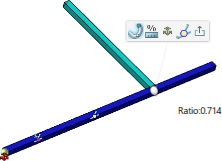
  1. In the 3D area, click a standard branch point.
  2. On the context toolbar, click Edit Branch Point .
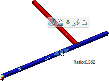
    A white bullet represents the branch point position and a red anchor icon indicates its reference point.

  3. To edit the branch point position, do one of the following:
    • Click the white bullet, and then position the branch point with your pointer along the curve.
    • Pause over the white bullet to display the manipulator, and then drag an arrow along the curve.

      The impacted branch turns red.

    • Click the Distance label, enter a value, and then press Enter.
      Tip: Click Change Branch Point Unit to display the relative position either in length or in ratio.
  4. To select another reference point:
    1. Click Change Reference Object .
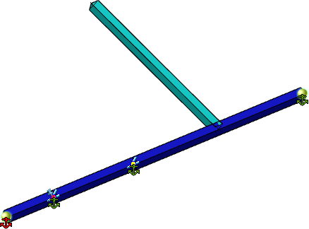
      The available route elements and branch points are displayed with a green anchor icon.

    2. Click an icon to select a new reference point.
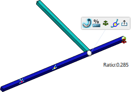
    The green icon turns red and the distance or ratio between the branch point and its new reference point is updated.

  5. To edit the branch point type, click Change to associative branch point , and then select a reference plane.
  6. To remove a branch point and select which segment to keep, click Remove Branch Point .
  7. Click Exit Branch Point Edition or click in the 3D area to validate your modifications.

Edit an Associative Branch Point

  1. In the 3D area, click an associative branch point.
  2. On the context toolbar, click Edit Branch Point .
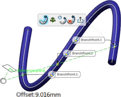
    • The view is reframed in an orientation orthogonal to the reference plane.
    • Intersections between the plane and the curve appear with a BranchPoint label, and yellow icons indicate the available intersections.
    • If an offset is defined between the branch point position and the intersection, it is displayed with green dots in the 3D area.


  3. To select another intersection, click a BranchPoint label.
    The yellow icon is updated to indicate the new position of the branch point: .

  4. To edit the offset between the branch point position and the intersection, do one of the following:
    • Click the Offset label and enter a value in the box.
    • Hover over the manipulator and drag it to edit the offset value.

      The manipulator can only be dragged in a direction normal to the selected plane.

  5. To select another reference plane:
    1. Click Change Reference Object , and then select a plane or a planar surface.
      Available intersections appear along the curve with a BranchPoint label.
    2. Click a label to position the branch point at the location of the selected intersection.

    Important: When you select another reference plane for a branch point positioned with an offset, the offset is kept and applied to the new position of the branch point.

  6. To edit the branch point type, click Change to standard branch point , and then edit the branch point position if necessary.
  7. To remove a branch point and select which segment to keep, click Remove Branch Point .
  8. Click Exit Branch Point Edition or click in the 3D area to validate your modifications.

Edit a Proxy Branch Point

Important: You can only edit a proxy branch point when a secondary branch is activated.

  1. In the 3D area, click a proxy branch point.
  2. On the context toolbar, click Edit Branch Point .
    A white bullet represents the branch point position.

  3. To edit the branch point position, do one of the following:
    • Hover over the primary branch to position the branch point with your pointer along the curve.
    • Pause over the white bullet to display the manipulator, and then drag an arrow along the curve.

      The secondary branch is impacted.


    • Click the Ratio label, enter a value, and then press Enter.
      Tip: Click Change Branch Point Unit to display the relative position either in length or in ratio.
  4. To select another reference point:
    1. Click Change Reference Object .
      Available route elements are displayed with a green anchor icon.

    2. Click an icon to select a new reference point.
    • The position of the proxy branch point remains the same.
    • The Length/Ratio, and Reference Point information are updated.


  5. Click Exit Branch Point Edition or click in the 3D area to validate your modifications.