.
.
 is activated and yellow bullets
 appear on route elements.
Create a First Passing Point with Offset and Generate the Curve
You can define an offset from a surface to add a new passing point to an existing route.
The position of this passing point is defined according to the intersection between a direction and the offset surface.
-
Click a passing point, and then click Route On Surface
 on the context toolbar.
Note: The command is not available if:
on the context toolbar.
Note: The command is not available if:- The selected point is a corner point. For more information, see About Multiprofile Branches.
- The selected branch has only one route element.
The Route On Surface panel appears. -
Under Offset, select the Offset
mode.
Option Description 
Center curve The offset is the distance set between the surface and the center curve of the branch.

Profile width The offset is the distance set between the surface and the height of the branch profile.

Profile length The offset is the distance set between the surface and the width of the branch profile.
-
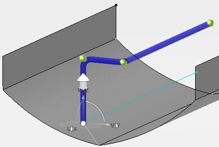
Under Intersection, select your preferred direction.
Option Description 
U axis The U axis of the Robot is used as direction to position the new passing point along the offset surface.

V axis The V axis of the Robot is used as direction to position the new passing point along the offset surface.

W axis The W axis of the Robot is used as direction to position the new passing point along the offset surface.

Branch direction The direction of the branch is used to position the new passing point along the offset surface.

No preferred direction The direction to position the new passing point along the offset surface is defined manually.
To do so, hover over the surface and use the manipulator snapped on the surface to position freely the passing point.
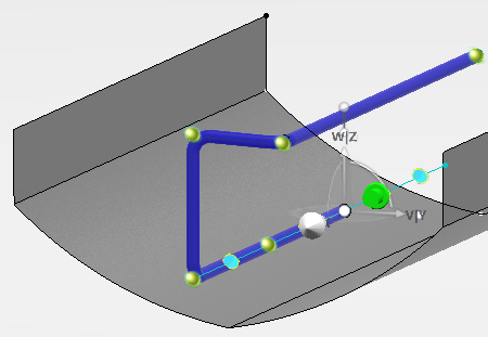
Tip: You can manipulate the Robot to modify the orientation of the U/V/W axis. -
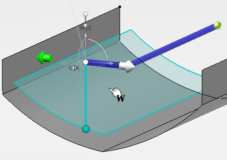
In the 3D area, hover
over a surface.
The offset surface and the passing point are previewed according to your parameters.
In the following example, the direction selected for the intersection between the branch and the surface is the W axis.
-
Click to add the previewed point to the route of the branch.
- The route of the branch is updated.
- A curve is generated. It corresponds to the intersection between a cutting plane and the offset surface.