You can place a connection point using multiple
constraints.
In this scenario, a cavity is added to a device. The scenario is identical for cavity connection point, backshell connection points, connector connection points, and shell connection points.
- From the Device section of the action bar, click Cavity
 .
. - In the tree or in the work area, select a device.
The Cavity Definition
dialog box appears.
- Select the Advanced tab to set the placement constraints.
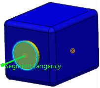
- In the work area, select a geometrical element (i.e. pocket, pad, face, etc.) to represent the connection
point.
This element lets you visualize the connection point in
the
work area and facilitates its identification while you
work.
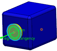
The selected geometrical element appears in the
Representation box.
- In the Constraining Geometry area, define one or more constraints depending on the degree
of desired freedom.
Valid geometries used to define the three degrees of freedom offered
are:
| Constraining
geometry
| | Valid geometry
|
|---|
| Contact
| (mandatory) | Surface or point |
| Coincidence | (optional)
| Surface, line or axis
|
| Orientation
| (optional)
| Surface, line or axis
|
Note:
Orientation is used to constrain the rotation i.e. the third
degree of freedom.
The type of constraint obtained depends on the
selected geometrical elements for mating connection points.
For example, you obtain a contact constraint only if, for mating connection
points, the degree of freedom is defined by two surfaces for both connection points.
If a point is selected, the constraint is a coincidence constraint.
| Surface | Point | Line |
|---|
| Surface | Contact
| Coincidence | Coincidence |
|---|
| Point | Coincidence | Coincidence
| Coincidence |
|---|
|
Line
| Coincidence
| Coincidence
| Coincidence
|
|---|
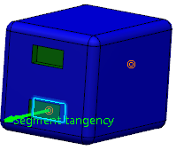
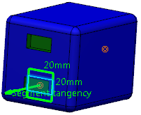
- Click More... to edit the dimensions of the cavity and visualize your changes directly in the profile preview in the work area.
- Click OK to validate.
The cavity is added to the selected device and appears under the Electrical node in the tree.
 .
.